 GREEN
GREEN
AND
CLEAN
POWER
French River Land Company's Website!
|
AND CLEAN POWER French River Land Company's Website!
|
|
French
River Land Company's Home Page!
Rebuilding 120" Niles Boring Mill HYDROELECTRIC SITES: Anasagunticook Lake Dam Replacement- C.Fay & W.Fay Appleton Wisconsin Anniversary Senor Bonifettis' sites in Chile Turners Falls Generator Rewind USEFUL ENGINEERING: Admitting Air to Turbine Runners Improves Efficiency, S. Logan Kerr Air Admission to Hydro Runners, David Cox, USCOE, Kerr Dam Archimedian Screw Pump Handbook- Gerhard Nagel A Self-Adjusting Spring Bed Bearing- Henry G. Reist ASME 1646 The Banki Water Turbine Mockmoore and Merryfield Bearing Currents: Their Origin and Prevention C. T. Pearce Bishops Method- STABGM Program Blade Pitting- Boving LTD 1930 Cavitation- Accelerated Research, Allis Chalmers Research Cavitation & Vibration of a Draft Tube Cavitation- Prevention & Reduction, Allis Chalmers Research Causes & Effects of Cavitation in Hydraulic Turbines Chain Turbine by: Nguyen Minh Duy Chain Turbine Mechanics- Discussions with Duy Characteristics of Modern Hydraulic Turbines-Chester Larner Comparative Tests On Experimental Draft Tubes- C M Allen & I A Winter 1923 Design of an Overshot Waterwheel (by Carl Weidner) Design of Small Water Turbines for Farm and Small Communities Design of the runner of a Kaplan turbine for small hydroelectric power plants: Timo Flaspöhler Draft Tubes of Hydro-Electric Stations by M. F. Gubin Ejection into Tailraces of Hydropower Plants: S. M. Slisskii Erection & Alignment of Vertical Waterwheel Generator Units-R.O. Standing Evolution of Hydraulic Prime Movers-Byron McCoy Fall Increaser Herschel Venturi Tube Fall Increaser Moody Ejector Turbine Fall Increaser Hydraulic Jump Apron Generator Shaft Design Calculation- Olav Hodtvedt Governor Theory for the Plant Operator Graphics of Water Wheels- William Fox Hydraulic Motors- M. Bresse & F. A. Mahan 1869 Hydraulic Power Transmission by Compressed Air Hydraulic Rams their Principals and Construction by J. Wright Clarke Hydraulic Turbine and Governor Field Erection Information Hydraulic Turbines- Robert Long Daugherty Hydraulic Turbines by Arnold Pfau Hydraulic Turbines Gelpke & Van Cleve Hydrokinetic Energy in Massachusetts, William D. B. Fay HYDROTURBINES DESIGN AND CONSTRUCTION N. N. KOVALEV Impulse Turbines by Ely Hutchinson Interference fitting a large runner shaft Kaplan Blade Design NACA Air Foil- Report No. 460 Kaplan Blade Design NACA Air Foil- Report No. 628 Kaplan Design Marko Kogovsek.xls A Laboratory Study to Improve the Efficiency of Crossflow Turbines- N. Aziz & V. Desai Loading Vertical Thrust Bearings R. C. Johnson Low Head Hydroplants, Emil Mosonyi Meggering Earth Resistance Motors as Generators for Microhydro, Nigel Smith Operation & Maintenance of Hydro-Generators Out Gassing of Cross Flow Turbines Parallel Operation of Turbines Analysis Powerhouse Design- Miniwatt Hydro Rack Design-Chicopee-Olav Hotvedt Rack Design- Hydraulic Institue of Munich Rack Design-Flow Induced Vibrations Selecting Hydraulic Reaction Turbines BUREC Snows Improved Water Wheel Governor Standard for Hydraulic Turbine and Generator Shaft Couplings and Shaft Runout Tolerances Stoplog Structure Design Calculation Stress Analysis of Hydraulic Turbine Parts, BUREC- F.O. Ruud Some Fluid Flow Characteristics of a Cross Flow Type Hydraulic Turbine- Durgin & Fay Technology of Heavy Electric Machine Building HydroGenerators Tenth Census of the US, 1880, Water Power of the US, Part I- Professor Trowbridge Tenth Census of the US, 1880, Water Power of the US, Part II- Professor Trowbridge Tests on a Kaplan Hydraulic Turbine Theoretical Conditions Related to an Open Channel Flow Linear Turbine- Ishida & Service Theory of Turbines- De Volson Wood Tidal Energy for Hydroelectric Power Plants by L. B. Bernshtein Treatise relative to the Testing of Water-Wheels and Machinery, James Emerson 1879 Trash Rack Differential Equations 2L/3 Trashrack Differential Equations General Solution f(x) Turbine Water-Wheel Tests- Robert Horton Turgo, A High Speed Impulse Turbine- Paul Wilson Water Hammer and Surge Tanks G. V. Aronovich Water Hammer-Lorenzo Allievi-Text Water Hammer-Lorenzo Allievi-Figures Water Hammer-ASME Symposium 1933 Waterpower Engineering-Daniel Webster Mead Water Turbines Contributions to Their Study, Computation and Design-S.J. Zowski TRADE CATALOUGES: ASEA- Bearings for Large Vertical Hydro-Electric Machines Bradway Turbine (progressive gate) Christiana Machine (register gate) Electric Machinery Company (EM) General Electric- Standard Specifications for Hydro Thrust Bearings and Runners Head Gate Hoists- S. Morgan Smith J & W Jolly (cylinder gate) Lombard Direct-Connected Oil Pressure Governors Bulletin N0. 113 October 1st, 1912 Lombard Governor Company Type T Instruction Book Lombard Governors for Waterwheels and Steam Engines-1902 Lombard Water Wheel Governors Catalouge 26 Ridgway Perfection Water-Wheel Vertical Shaft Water Wheel Driven Generators- General Electric Westinghouse Small Vertical Waterwheel-Driven A-C Generators, July 1944
Links:
Small Turbine Manufacturers Websites: www.waterturbine.com
|
Previous Pictures Four Web Page June 30th, 2012 Karen and I have been restoring the Woodward Governor that Johnie Webster sold me. I still need to install the motor and piping.
June 9th, 2012 I picked up the used Atlas Polar trashrake from the Mechanicsfalls HEP north of Albany today and brought it back to the shop. It was a miserable trip. I got the tongue pressure too high and the truck wanted to jacknife over 45 mph. It was a long trip home. We are rebuilding the rake and installing it at our Indian River plant:
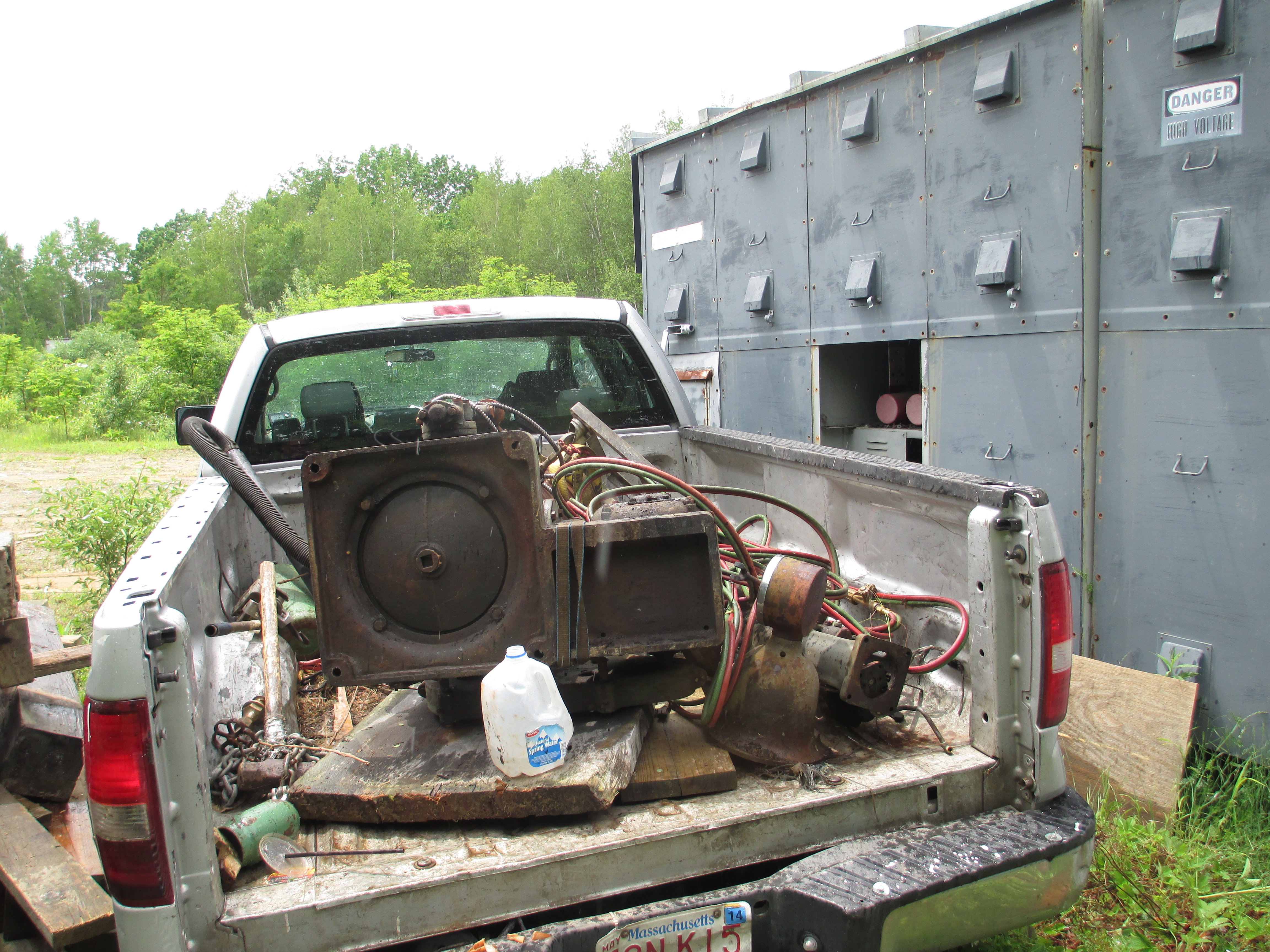
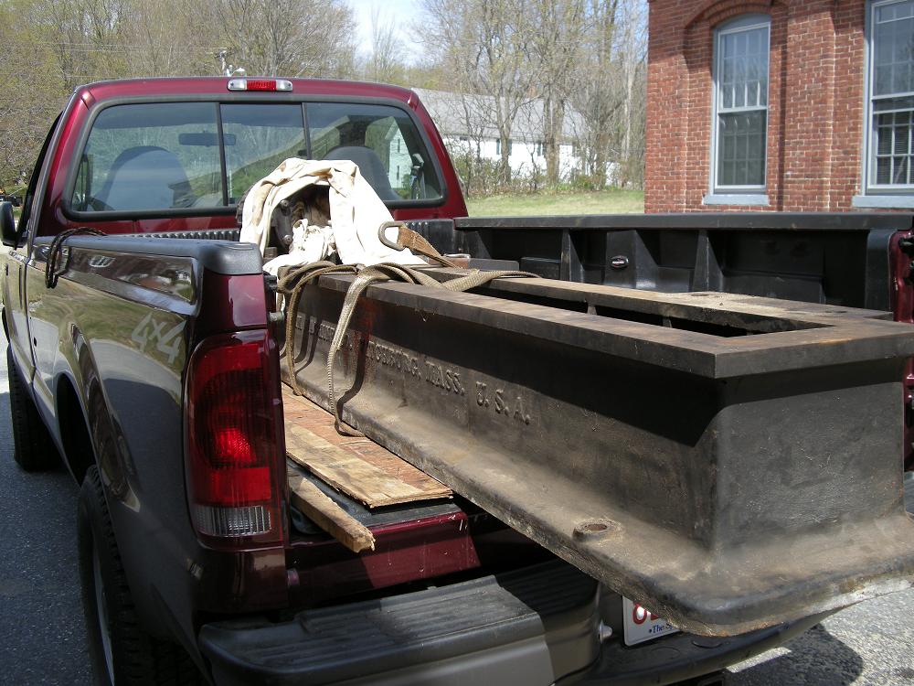
How do you load a 500 pound Woodward governor pump, into a pickup truck, without a crane and without someone to help you?
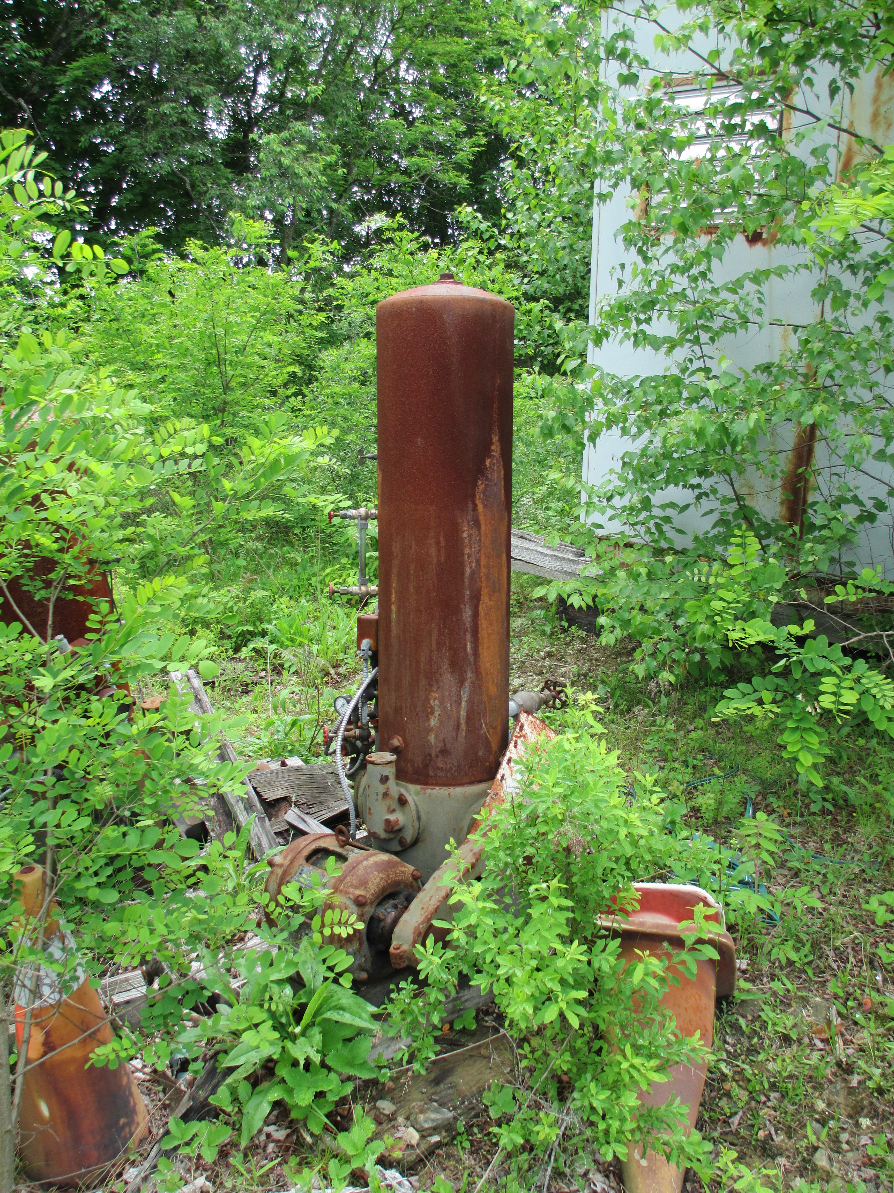
Here is the Woodward Pump as I found it in the back of Johnie Webster's junkyard. It was in the bushes and nearly inaccessible behind an electrical enclosure and a pile of cribbing.
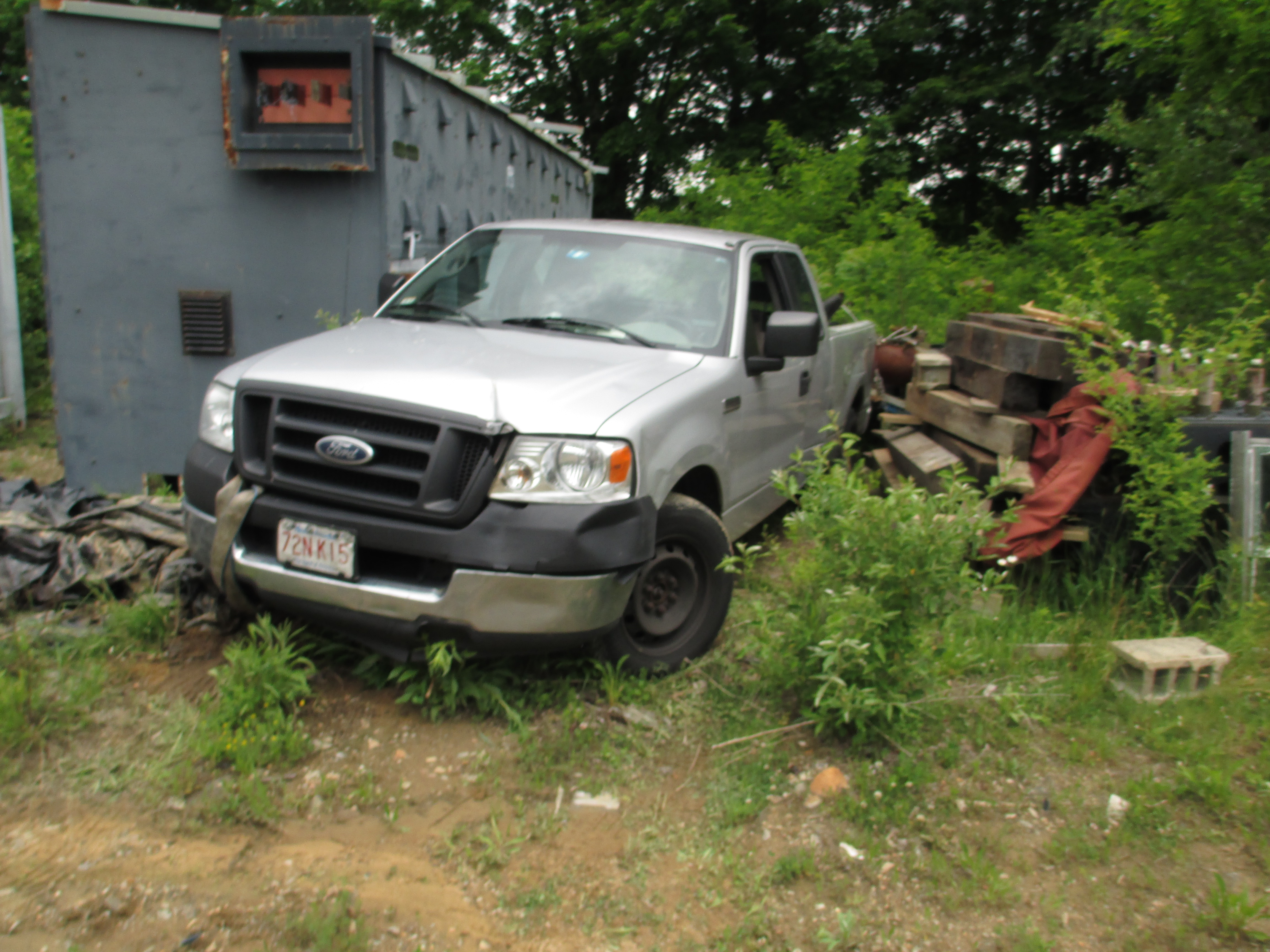
I had to move some of the cribbing and back the truck in between the cabinet and the cribbing. It was about then that it started pouring. The governor pump is off to the side at an angle to the truck bed.
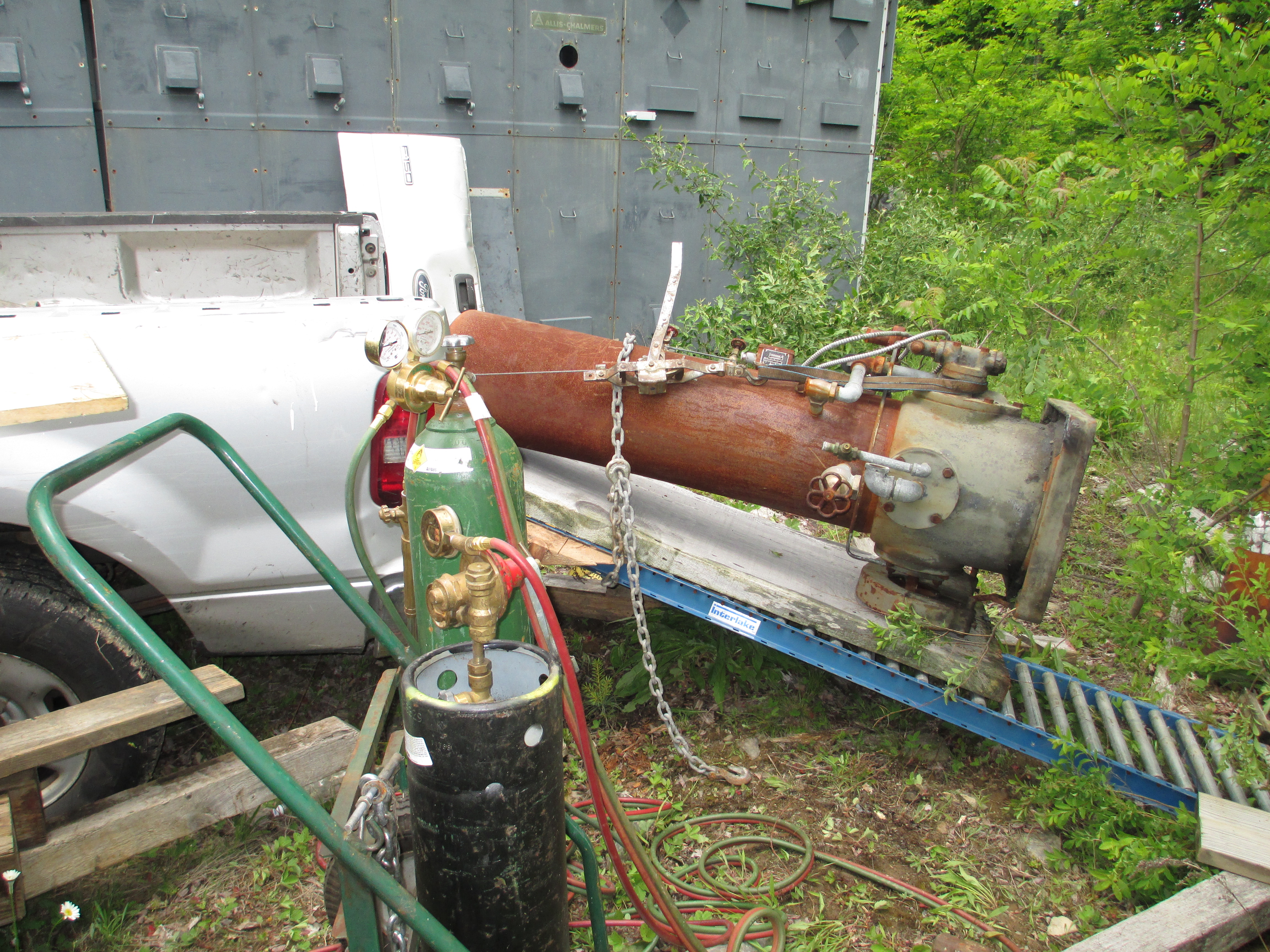
Here, I have chained the top of the board to the top of the governor pump to keep it from flipping up, off of the board. I pulled the pump up the roller table and it suddenly stopped. The chain had hit a 2x4 that I had used to create clearance between the bed wall and the roller table. I had to let the pump back down the roller cable about 6 inches. I used a ratchet strap to hold the pump down to the board. I removed the chain and resumed pulling the pump up the roller table.
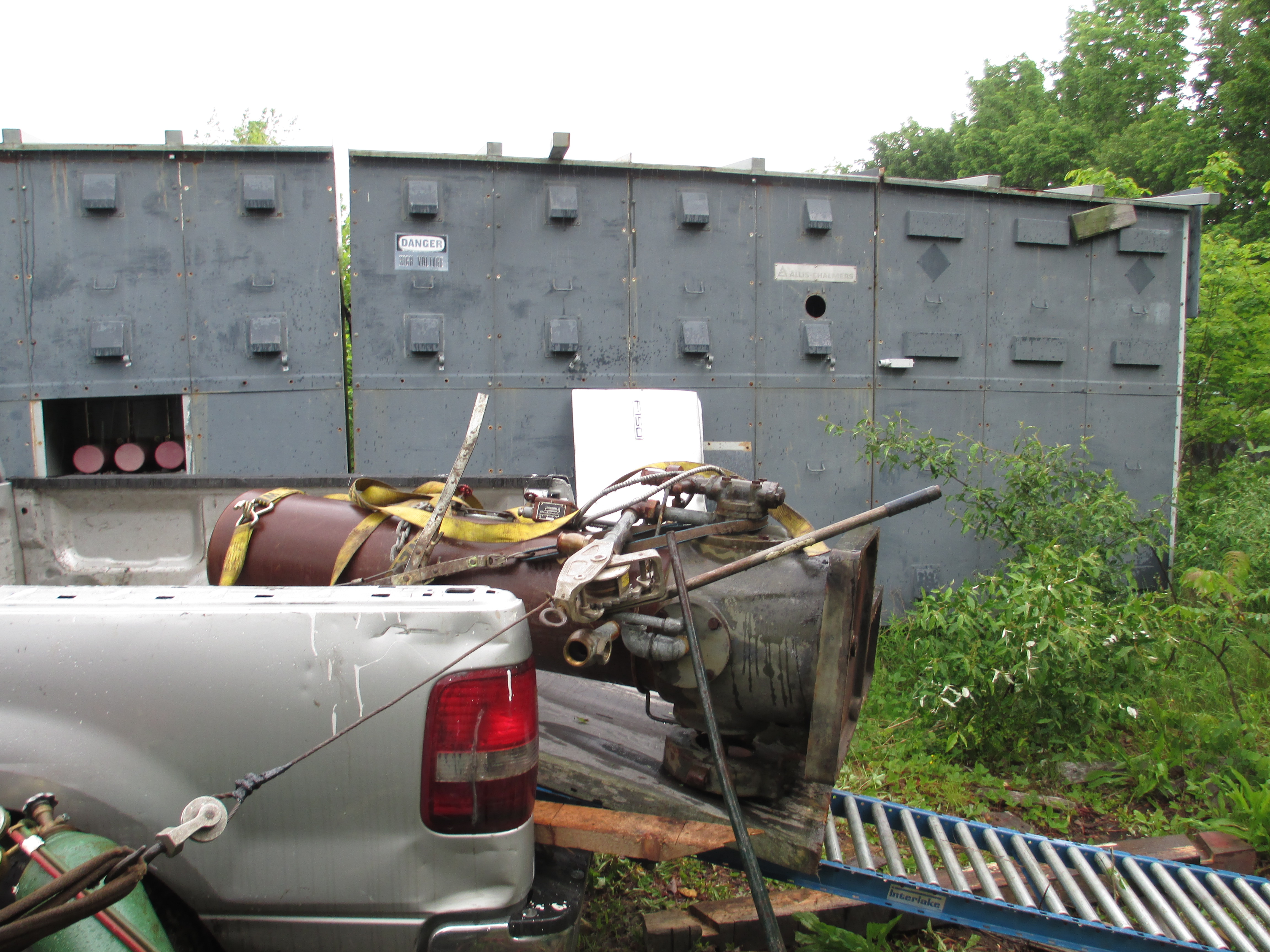
I brought this roller table with me. I had to take the tailgate off of the bed. I angled the roller table so that one end rested on the bed and the other end was in front of the pump. I found a rotting slab of wood and placed it on the roller table. I carefully tipped the pump onto the slab of wood. I attached two cum-a-longs to the pump. One cum-a-long was used to pull it into the bed. The other cum-a-long was used to keep it from sliding sideways off of the roller bed. I slowly worked both cum-a-longs and pulled the pump into the truck. When most of the weight was on the truck bed, I used a 6 foot wrecking bar to lever the bottom end of the roller table sideways to align it with the truck bed. I had to do this to gain some side clearance to allow some pump piping to slide into the bed.
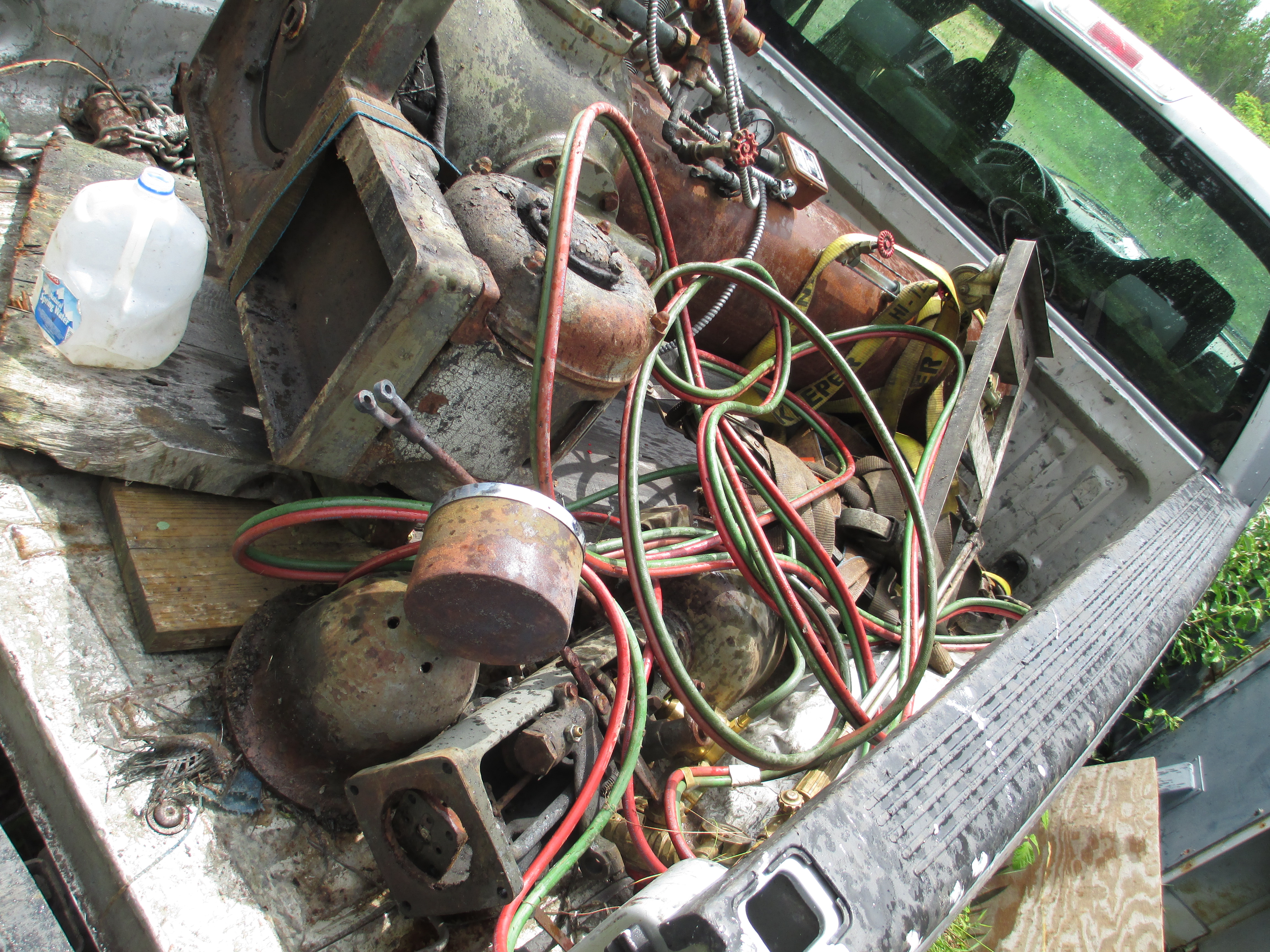
Here is the pump resting comfortably in the truck bed.
I went back and removed the motorized flyball head from the Woodward governor. I am pretty sure the pump and governor came from St. Mary's Kansas. The governor had been stored outside for 20 years with the cover removed. It is in really rough shape. Additionally, the top of the rotor was broken off. I needed the motorized head for parts.
June 6th, 2012 I was given this GEH manual on water wheel generators by Pablo Juan Thomasset from Uruguay.
He works at the Rincon del Bonete hydroelectric project. Rincon del Bonete Powerhouse <<<< click here for a PDF of Jefe Juan Thomasset's HEP They had a massive flood in 1959 that is documented here:
May 25th, 2012 I had an exceptionally interesting week. On Wednesday I met with the Belchertown Land Trust, the "Save the Dam" folks, the Director of Mass Dam Safety, the Commissioner of DCR and interested parties regarding saving the Upper Bondsville Dam that impounds the Swift River below Quabbin Reservoir. On Thursday, Wayne Bailey and I met with Jim Besha, the owner of the Mechanicsville Hydroelectric Project that is constructed across the Hudson River. He is graciously selling us an Atlas Polar trash rake for our Indian River HEP. Today, I met with Gerald Cross, the Director of the New York Office of the Federal Energy Regulatory Commission. Chief Inspector Cross was a delightful person. I was amazed that he would come in person to inspect our Pepperell HEP. We had a great discussion and he was very informative. We discussed flashboards and the fact that there have been a great number of instances where flashboards have not failed during design floods. It turns out that in the 20s, 30s, 40s, 50s, 60s and 70s flashboards were designed with 36 ksi steel. People can not find 36 ksi bar stock. They have been replacing their pins with rebar. The problem is that rebar is 50 ksi!! So the pins have not been failing when they were supposed to. Chief Inspector Cross also spoke about the alarming effects of climate change. The water is coming faster and there is more of it. Dam spillways that were designed with a 1930s maximum flood can no longer safely pass the floods that are occurring. Everyone is worried about dam safety!!! Chief Inspector Cross is concerned about the erratic failure of flashboard pins. He would prefer that some type of hinged, hydraulically controlled boards be installed on dam crests in leau of flashboards. I greatly enjoyed speaking with him!!!! He is a very down to earth guy.
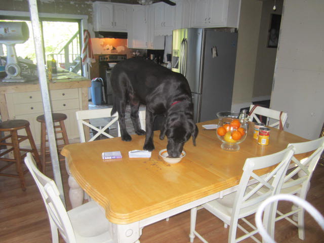
I have four dogs and two cats. For the last several months we have mysteriously been using an enormous amount of cat food. We decided to keep the cat food in the middle of the kitchen table. Last Thursday, I was up early getting ready to drive to my Turners Falls HEP. I heard a noise downstairs in the kitchen. When I came around the corner here is what I found:
Busted!!!!!!!
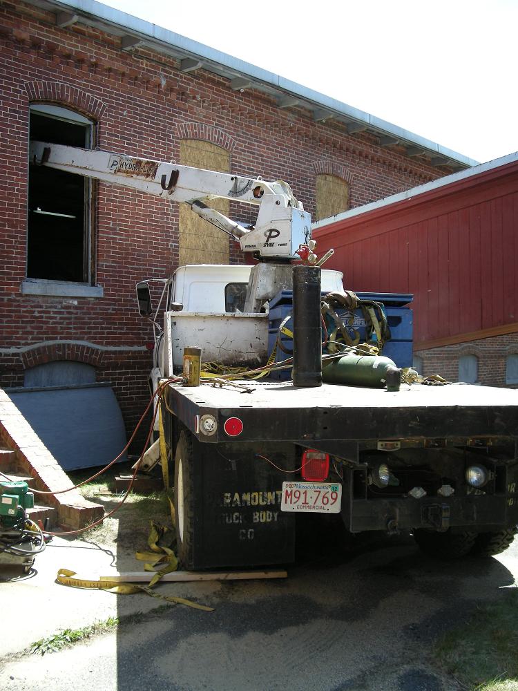
May 20th, 2012 I forgot that Peter took some photos of me pulling the steam engine bed out of the cotton mill. He just sent them to me.
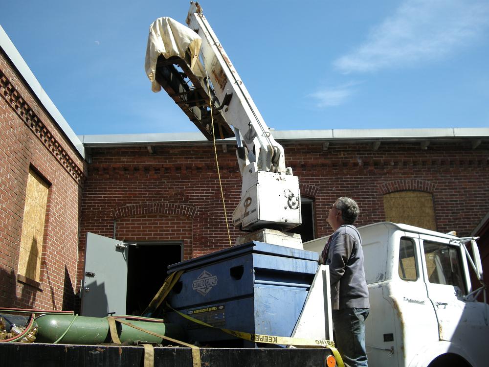
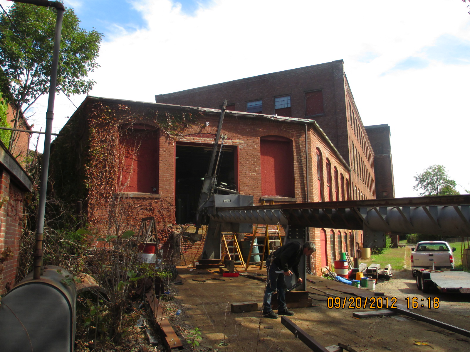
I had to poke the boom through the mill window and then drive forward in able to get my hook over the steam engine bed. Once I was lined up, I put my feet down and started the pick. If you look closely, my fender is against the wall of the building. The problem with this position is that the weight of the pick was mostly on the front axles of the truck instead of on the feet. As I pulled the bed up from the basement, through the hole that Peter had cut in the floor, the truck started to sink onto its springs. I barely got the bed out of the window. In order to fully extract the bed and due to the rotten mill floors, I had to partially balance the steam engine bed, on the brick window sill, while I lifted my feet and backed the truck up so that I could swing the boom around.
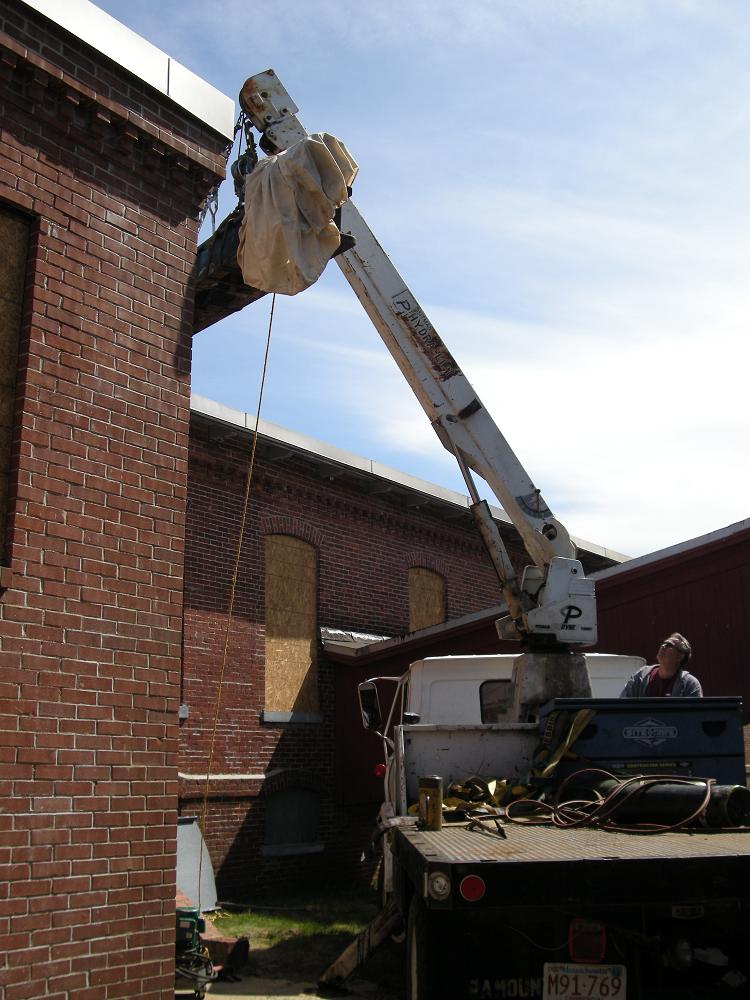
Here, the 4000 pound steam engine bed has come out through the window. I am swinging it broad side to the truck. This is the most dangerous position to be in because the weight is trying to flip the truck over. It was so tight, in the little courtyard, that I now had to lift the bed up and over the corner of the building, in order to swing it behind my crane truck and load it onto Peter's trailer.
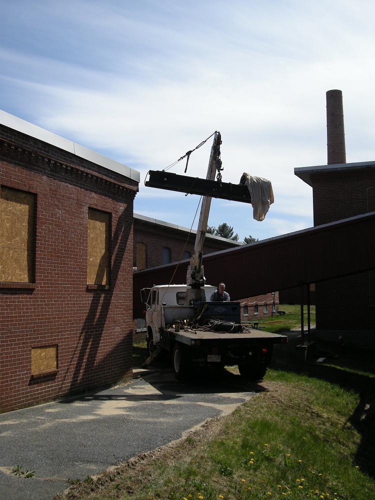
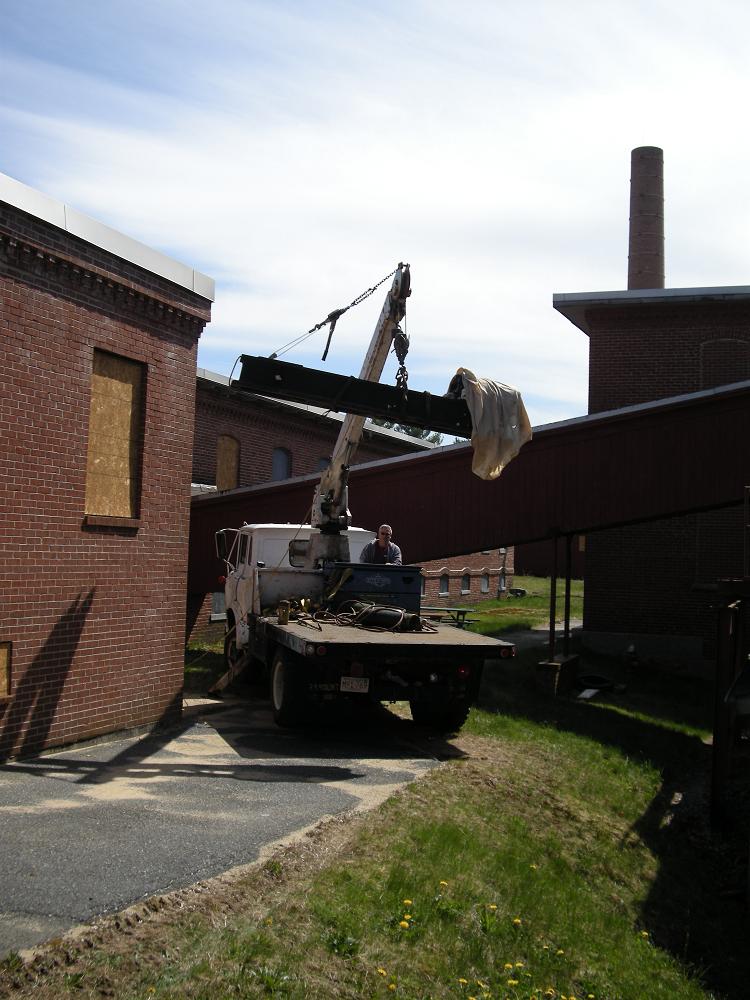
Here I have picked the steam engine bed very high and I am swinging it over the corner of the building.
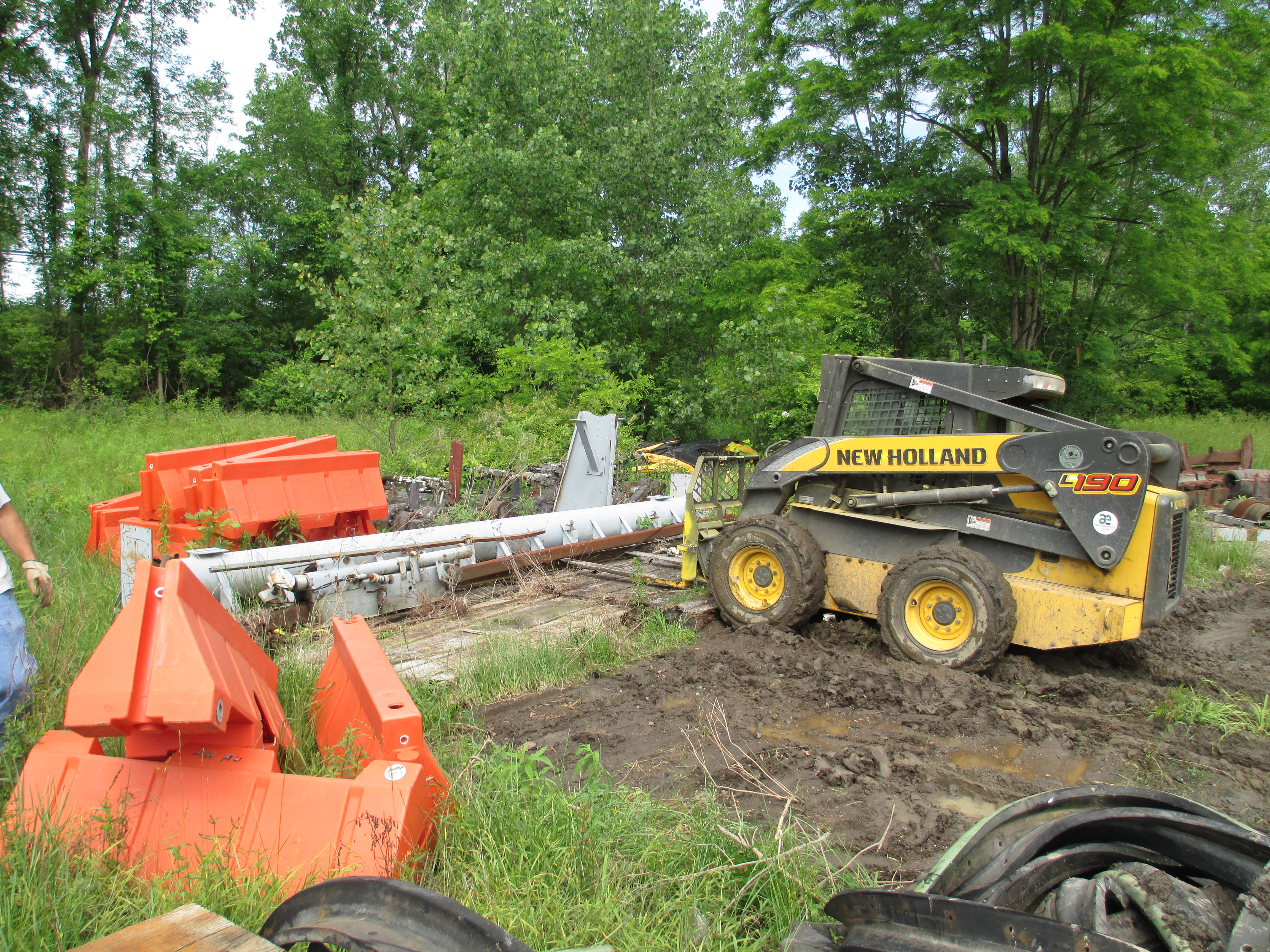
Look at this horrible place I drove my truck into. The slope on the right side was very soft and becomes very steep. Notice the depth of my tread marks, in the soil, next to the macadam. I hurt the driver's side door of the truck on an ornamental cast iron railing getting the truck in. I was very concerned about driving the truck out. I went in head first. I now needed to back the truck out. We had to build a temporary bridge with 8x8x16 foot southern yellow pine timbers to drive the truck out.
Here the bed is finally being lowered. Peter went to get his trailer.
Here is the steam engine bed sitting in Peter's truck ready to go back to his workshop. This left the 5000 pound cast iron flywheel in the cellar. I could not use the crane to pick it up. I came back several days later with my son, Will. I brought a pickup truck full of cribbing and an 8 inch high by 20 foot long aluminium riggers I-beam. We built two 8 foot high cribs on either side of the hole in the floor. We set the I-beam on the cribbing and secured it with heavy ratchet straps. Will went down to his Tannery Pond Hydrostation and took a beam trolley off of his ceiling mono rail. We reset the trolley's spacer washers for the 8 inch I-beam and installed it. We hung a three ton aluminium chainfall on the trolley. We lifted the flywheel out of the cellar. We hung a second chainfall from a strap on the I-beam. We rotated the flywheel flat. We slipped two, 16 foot by 8" by 8" southern yellow pine timbers beneath the flywheel and spanned the hole that Peter had cut in the floor. We put my four caterpillar machinery rollers on top of the timbers and under the rim of the flywheel. We lowered the flywheel onto the caterpillar rollers. We hooked a cum-a-long to one of the ceiling columns and attached the other end of it to the flywheel. We centered the 3 ton chainfall over the flywheel and reset the straps so that the flywheel was just barely hanging by the three ton chainfall as a safety. Will started ratcheting on the cum-a-long while Peter and I stood by with 12 pound sledge hammers to knock the rollers parallel to the southern yellow pine timbers. We held our breath while Will ratcheted away. The flywheel started to move sideways over the abyss. It worked flawlessly. We soon realized we did not need the aluminium I-beam, trolley and piles of cribbing. In fact one pile of cribbing was in the way of progress. We removed the beam and cribbing. I had brought four southern yellow pine timbers. In order to keep on spreading the load across the rotten flooring, we kept flip flopping the timbers end for end. The only anxious times was when we rolled across the abutting ends of the timbers. The support was the weakest at these points. It was still fine. When we wanted to turn a corner, we pointed the timbers in the direction we wanted to go. When the first set of caterpillar rollers touched onto the angled set of timbers, we smacked the rollers until they were aimed down the axis of the turned timbers. We continued to roll forward. We finally got to the concrete floor that lead to the loading dock. We extracted the crane from the court yard and drove it around to the loading dock. I ran my cable out to the flywheel and dragged it to the truck. I lifted it onto Peter's trailer.
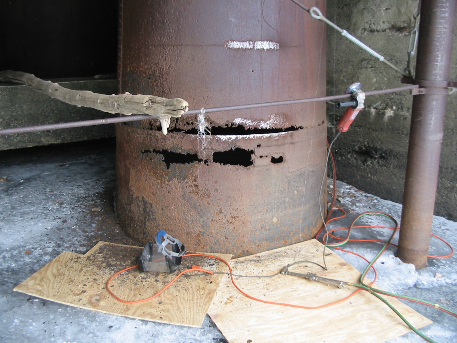
May 19th, 2012 I spent the last week repairing our unit at Turners Falls. The 900 kilowatt I.P. Morris turbine went into overspeed when we tried to shut it down. We dropped the head gates to try to control it but the left headgate would not close all the way. We turned the air controlled brakes on. The unit slowed to a low rotation, smoke poured out of the generator from the frying brake material and it continued to turn. We over rode the air compressor switch and pumped the air compressor pressure up from 150 psi to 300 psi and the generator finally stopped rotating. When we went down to the sub basement, we heard water coming from a crawl space next to the scroll case. It was pouring out of a pipe chase. We forced the headgate down with two 50 ton porta-power rams. The gate would not close the last 5 inches. Something was caught beneath it. The gates are 8 feet wide by ten feet tall. Their sill is 27 feet below the water. We chained off the generator rotor and opened the wicket gates. The penstock drained down but still had about 7 feet of water left in it due to the gate leakage. We noticed that when the penstock drained down the water stopped pouring out of the wall. We shut the wicket gates and refilled the penstock. The water started pouring out of the wall again. We reopened the wicket gates and somewhat drained down the penstock. Once again the water stopped pouring out of the basement wall. We decided we had a breach in the penstock wall.
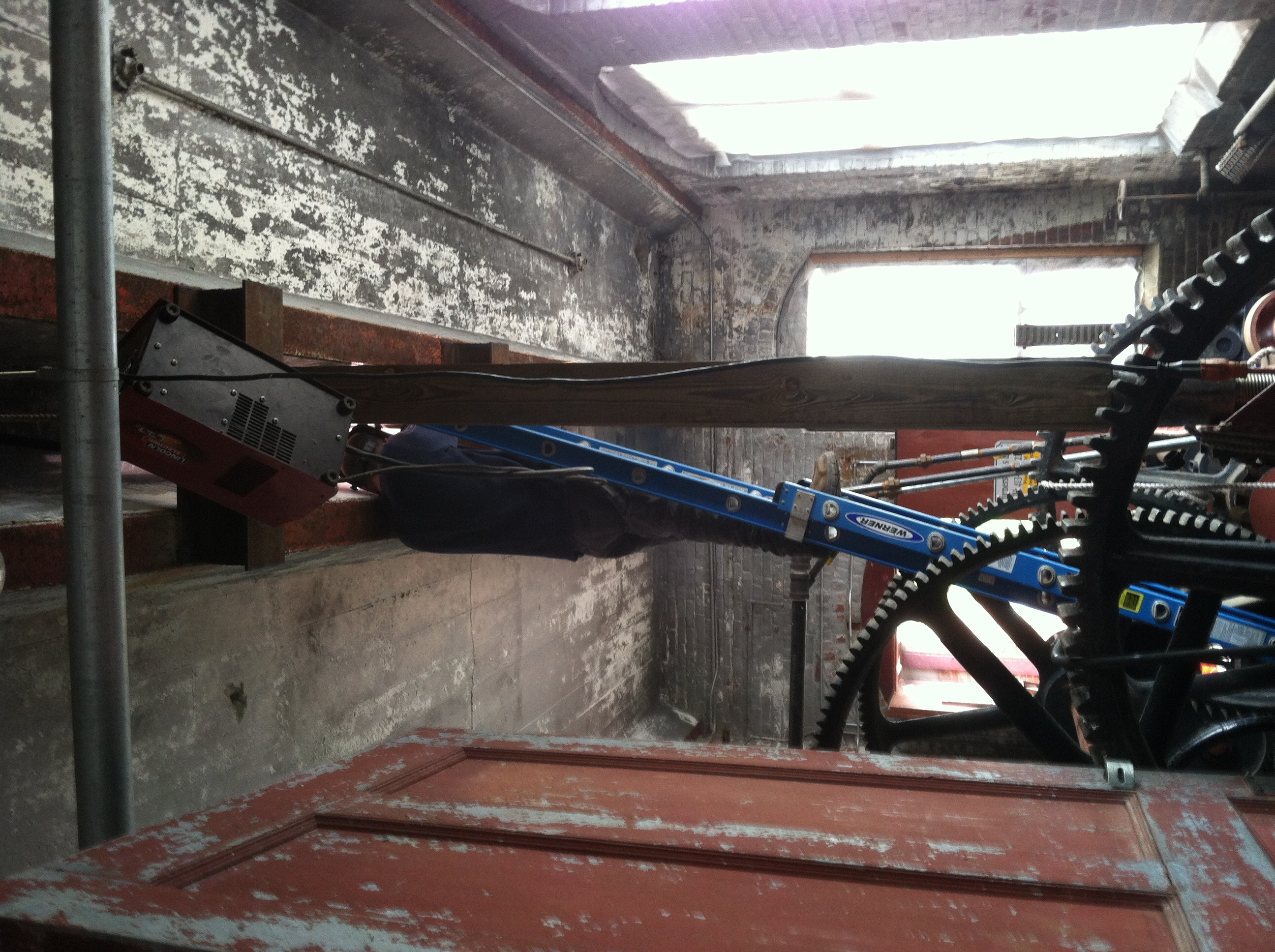
Photo One: We have installed these temporary 8x8 jacking posts. They are setting on top of the 50 ton porta-power cylinders. The cylinders are sitting on top of the gate stems. The other end of the posts are bearing against a short I-beam we have welded across the gate removal slots in the ceiling of the gate house.
In order to open the scroll case hatch we needed to stop the water flowing beneath the one gate. We got a piece of four inch steel pipe. The distance between the gate stems was 49 inches. We cut the the pipe to 48 inches. We installed 5/8 inch eye bolts in both ends of the pipe. We lowered the pipe down on cables. When it got to the bottom we could feel it being tugged beneath the gate. We pulled it back up. I went to the plumbing store and purchased a ten foot long piece of 6 inch diameter, PVC pipe. We cut a 48 piece long section from the ten foot length with a Sawzall. We slid the steel pipe into the plastic pipe and installed the eyebolts through the walls of both plastic and steel pipes to help weigh the plastic down. We lowered it down and felt it get sucked against the crack between the bottom of the gate and the sill. The distance from the gate stem to the side walls is 24 inches. We made two similar pipes that were 22 inches long. We lowered those pieces down to help seal the sides. We went down and cracked the scroll case manhole cover. We still had water seeping out of the top of the cover. We went back up to the gatehouse and filled 30 sandbags with sand. We tied 40 foot lengths of rope to the bags. We lowered the sandbags down until we felt them being tugged into the crack. We tied them off on the gate lifter. We installed 27 bags and finally got the gate sealed. We opened the manhole and entered the scroll case. We found a three inch diameter hole in the penstock about 1/2 way up the penstock towards the wooden gates and 1/2 way up the penstock diameter. It is a 13 foot diameter steel penstock that was installed in 1917. We cleaned the metal around the breach, fabricated a patch from 3/8 steel plate and welded it back on.
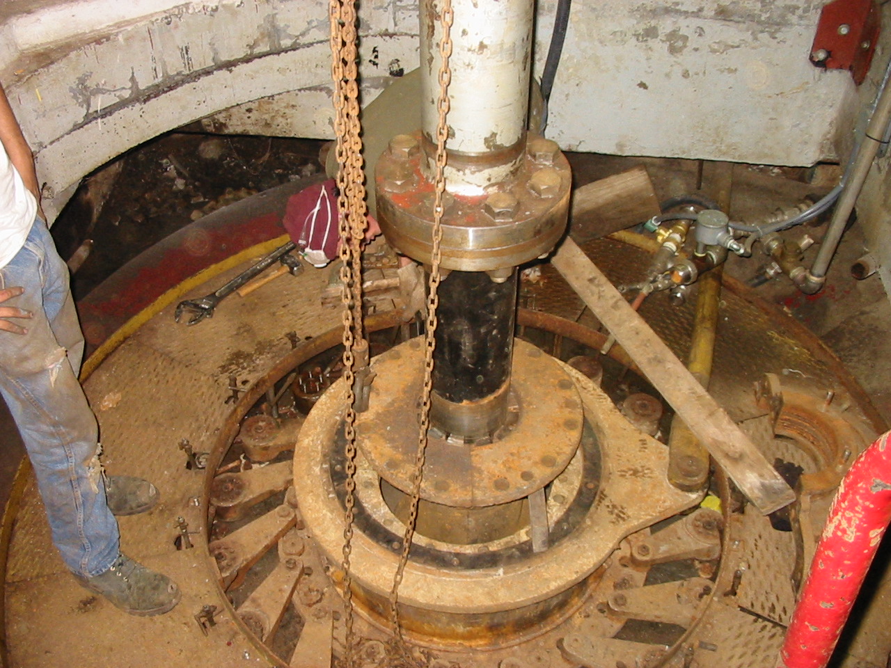
Photo Two: Here is the top of the scroll case. You can see the bell cranks that operate the wicket gates. Carefully notice the row of Allen screw heads that form a circle of black dots around the top of the big end of the bell crank. We inspected the turbine. GE Hydro had rebuilt the gatecase in 1997. They retrofitted the wicket gate bell cranks with Ring Phetters. One of the gates was open by 6 inches with the other gates in the closed position. We removed the ring phetter and removed the bell crank. We quickly noticed that the back end of the bell crank was cracked. Someone had over torqued the ring phetter Allen screws and it cracked the back bone of the bell crank. The wicket gate was loose and it finally slipped. Mike Desrouche ground out the bell crank and filled it with 7018. He than took a piece of 3/8 inch thick by three inch wide trash rack stock. He clamped the bell crank in the big vise. He clamped the strap stock to the bell crank. He heated the strap stock with our big oxyacetylene rose bud. As the stock turned red he forged the strap stock into a semi circle around the back side of the bell crank. When it was bent all the way around, he cut off the excess. He than welded the strap to the back side of the bell crank with 7018 to increase the strength of the repair rod filler of the bell crank crack repair.
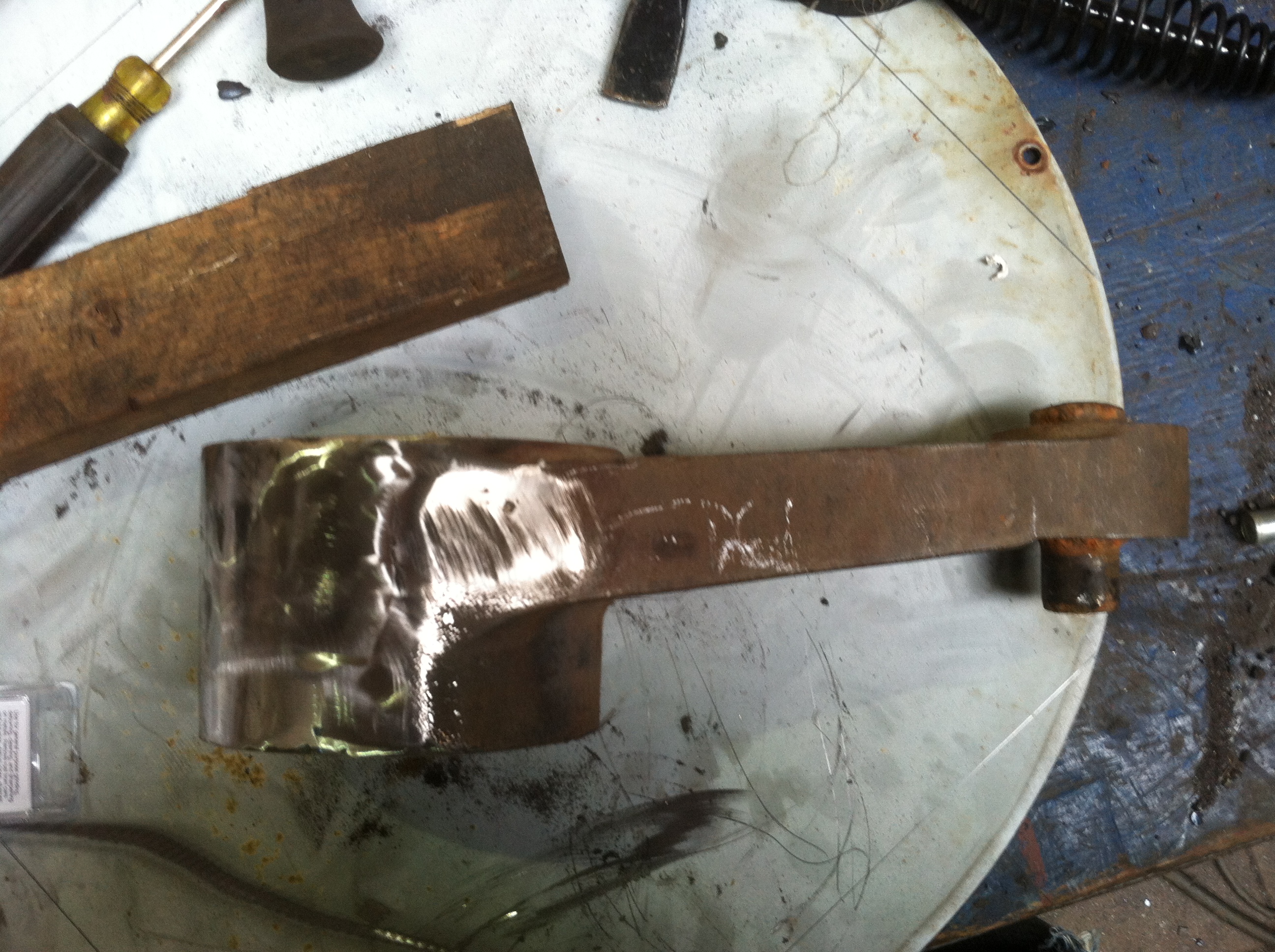
Photo Three: Newly repaired bell crank before the back strap was added and welded on. The crack was right down the middle of the shiny weld. We installed the bell crank. Yesterday, we removed the sandbags on a string and the pieces of pipe on a cable. We opened the headgates and restarted the unit.
Photo Four: Our 900 kilowatt, Westinghouse generator driven by our newly repaired I. P. Morris Francis turbine in operation.
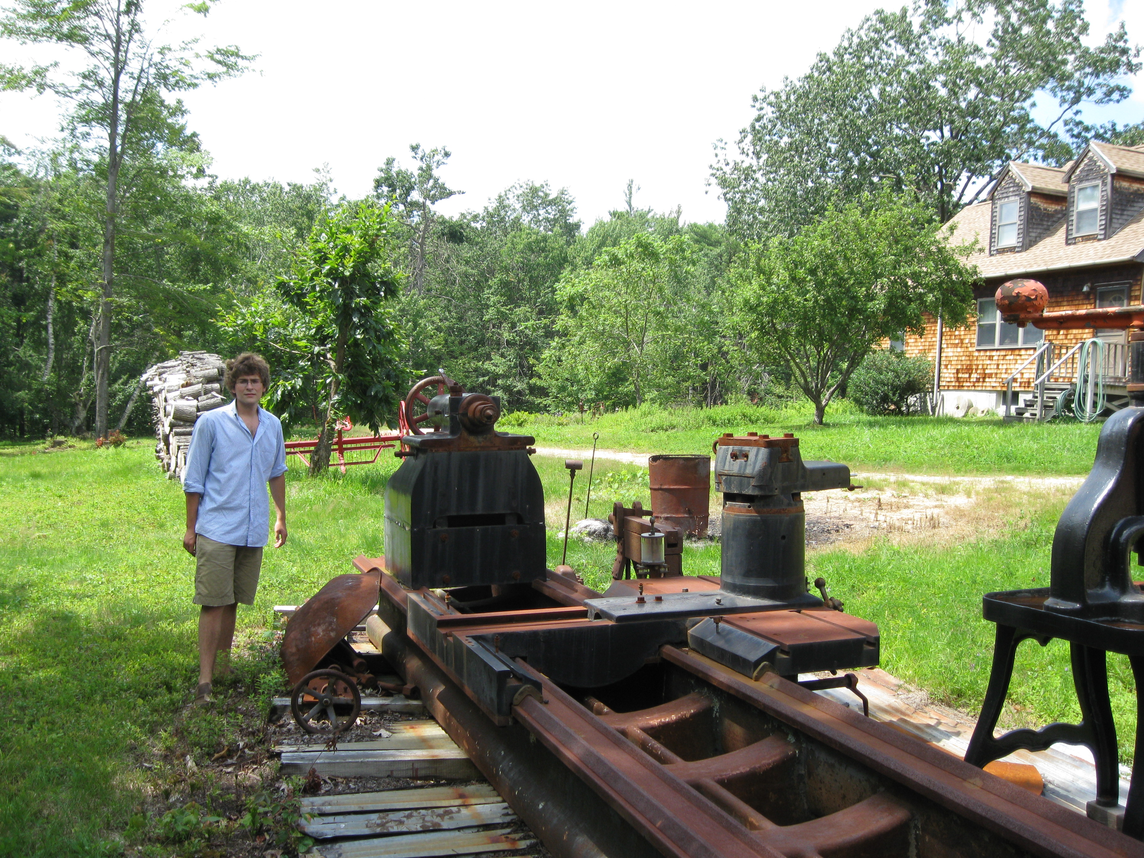
May 9th, 2012 I spent the last two weekends removing an 1850s Putnam steam engine from a sub basement of an old cotton mill. I forgot my camera, so no pictures. Peter traded me his Fitchburgh engine lathe for removing the engine. I am very excited to own the lathe. It has a 72 inch faceplate. I will retrofit it with a hydraulic drive and have the ways re-scraped. Here are some pictures of the lathe.
This is a beautiful lathe. It is 150 years old. I will put it back into production. I just need to find a place to put it.
Will is just over 6 feet tall. That is a huge face plate!!
Note the previous owners had retrofitted the lathe with a silent chain drive. Note the change gears are missing. I can still purchase these gears from Boston gear.
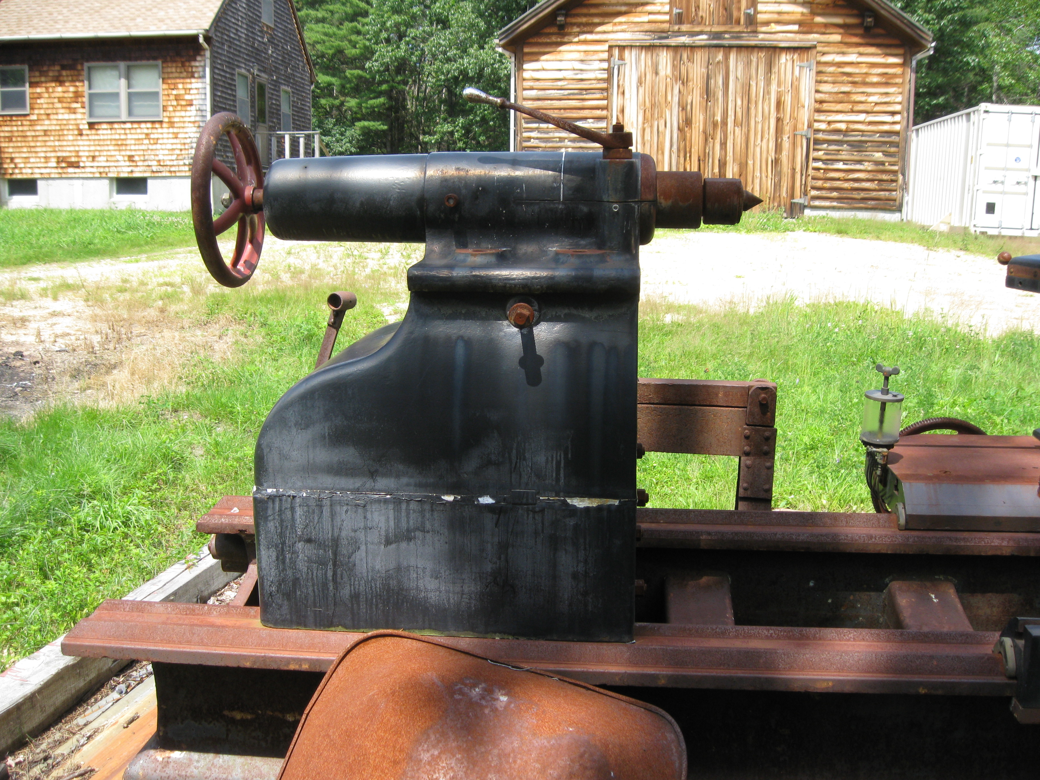
A view of the tailstock. I think very big guys ran this machine.
Another view of the tailstock.
How do you repair a draft tube? You wait until the ice is 18 inches thick and you use the ice for staging! The normal water depth here is about 14 feet. It needs to be that deep because the 1700 kW unit discharges at the back of the pit and the water needs to flow beneath the two smaller units' draft tubes.
April 5th, 2012, I share the following e-mail on generator upgrades with you: "As an example, the Hagley Generator was originally installed on 16 feet of head and was rated at 240 kw in 1928. In 1979, GE rewound the generator for 500 KW. To this day, the generator has two nameplates on it. They are the original nameplate of 240 KW and the rewind nameplate of 500 KW. This is circumstantial evidence that it is possible to achieve substantially more power out of an older hydro generator when it is rewound with new, plastic insulation. The generator manufacturers in the 1920s to 1940s designed for 50% saturation of the stator core. This means you still have 50% more magnetic capability if you can get 50% more current in the stator coils. In the early part of the last century, before the advent of plastic insulating material, the insulation consisted of cotton impregnated with tar and later on, asbestos mixed with tar and cloth coated, to insulate the copper wire. This was very bulky. The metal stator slots, that the wire windings fit into, had to be wide enough to fit the copper windings with their bulky insulating skin. This made for huge slots. If you take one of these generators and strip all the winding material out, you need to fill it back in with modern windings. The problem is, the new windings are insulated with thousandths of an inch thick plastic insulating material instead of 1/8 inch thick cloth/tar insulating material. The generator rewinder can not buy windings with bulky skins. They have no choice but to fill the slots with 50% more copper in order to fill the stator slots. This makes for a more costly rewind when compared to 1920 equivalent dollars. If you can not use the additional capacity capability, you receive a generator with an enormous service factor. The generator runs cooler than the 1920's generator. If you move the turbine to a higher head and produce more power or if you install a turbine that makes more power, in the original setting, the generator can produce the larger power output." Please see the following IEEE Paper on generator upgrades:
April 2nd, 2012, added "Low Head Hydro Plants", by Emil Mosonyi in side bar.
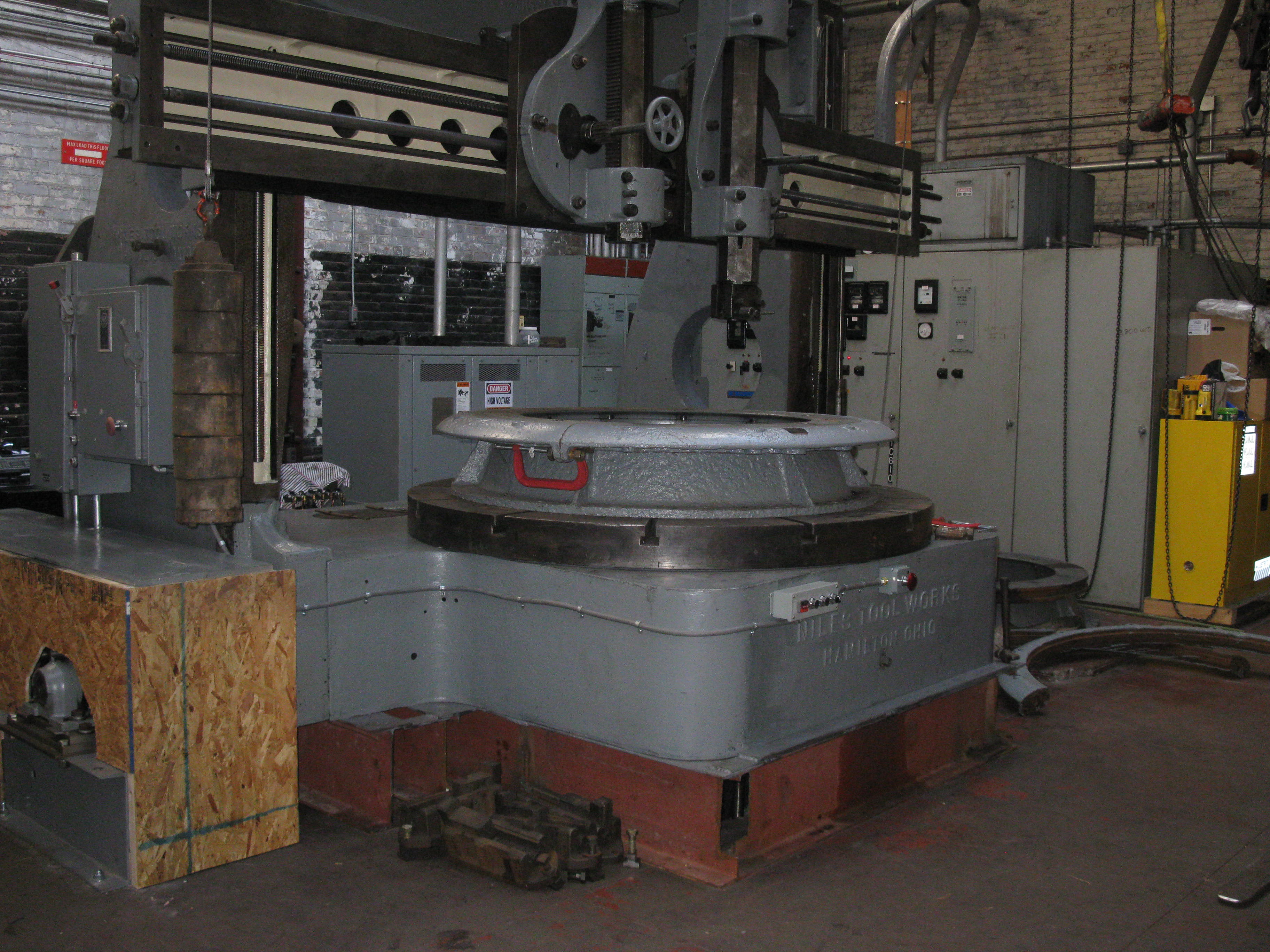
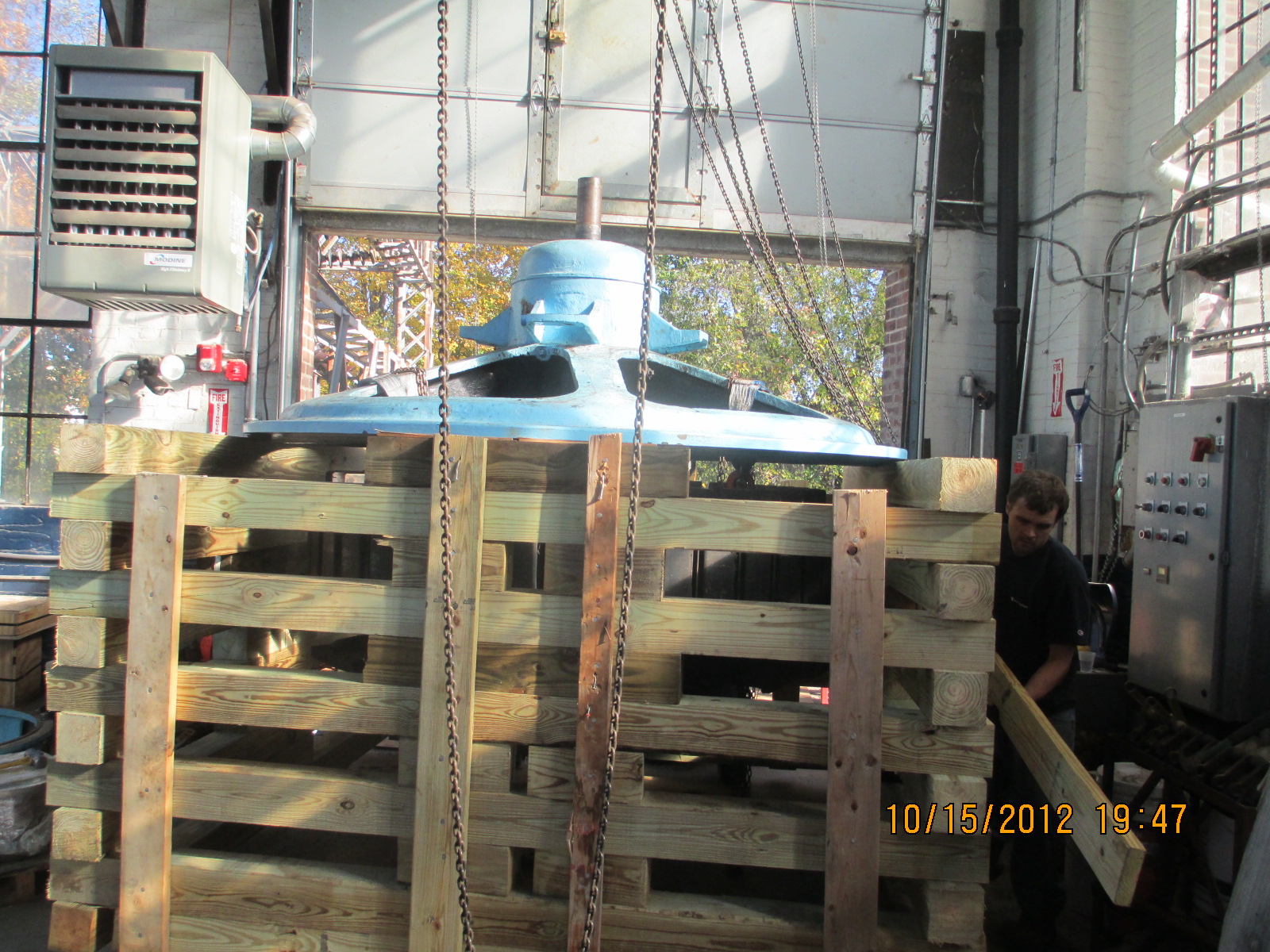
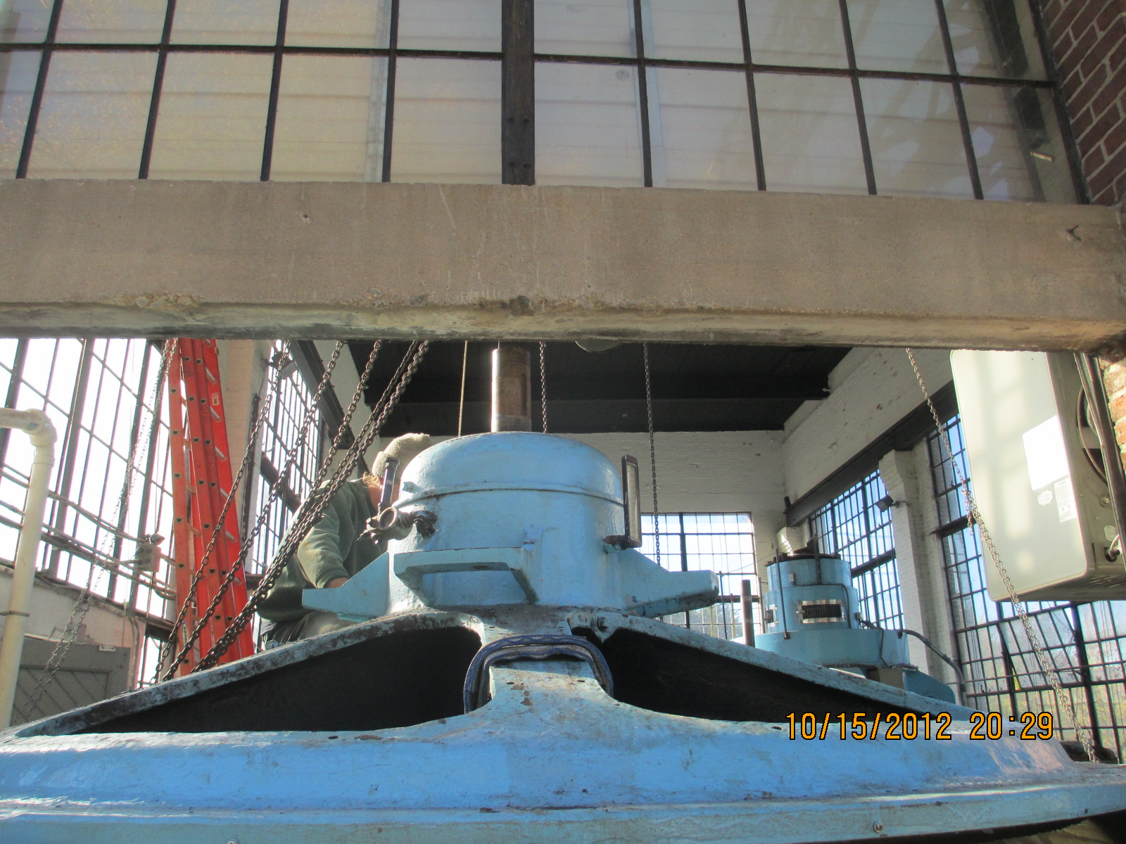
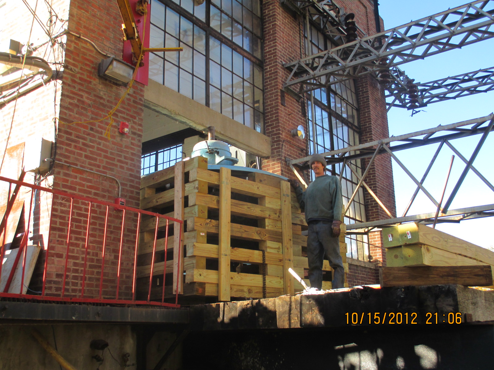
Turning a turbine throat ring on the newly restored Niles Boring Mill. Please see: Rebuilding 120" Niles Boring Mill<<< click here
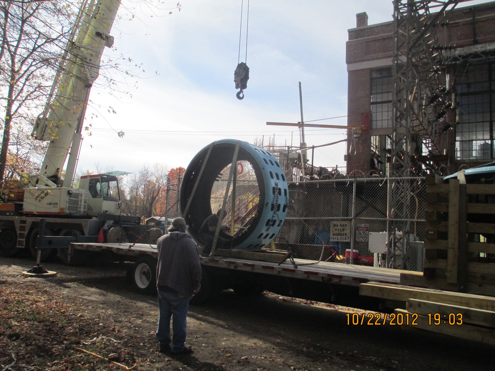
October 25th, 2012 We loaded the stator and rotor assembly onto a gypsy trucker's flatbed and sent it to Stultz Electric in Augusta, ME. It is the former Westinghouse rebuild shop. The stator stacks had delaminated and it sounded like a hive of angry bees had nested inside the generator stator walls. The generator will be restacked and rewound. The trucker showed up without the wide load permits. We were going to ship the stator lying flat (stable equilibrium). We had to ship it on edge like a coin (unstable equilibrium!!). It must have looked funny to the commuters on Interstate 95!
We have removed the rigging from the crane hook
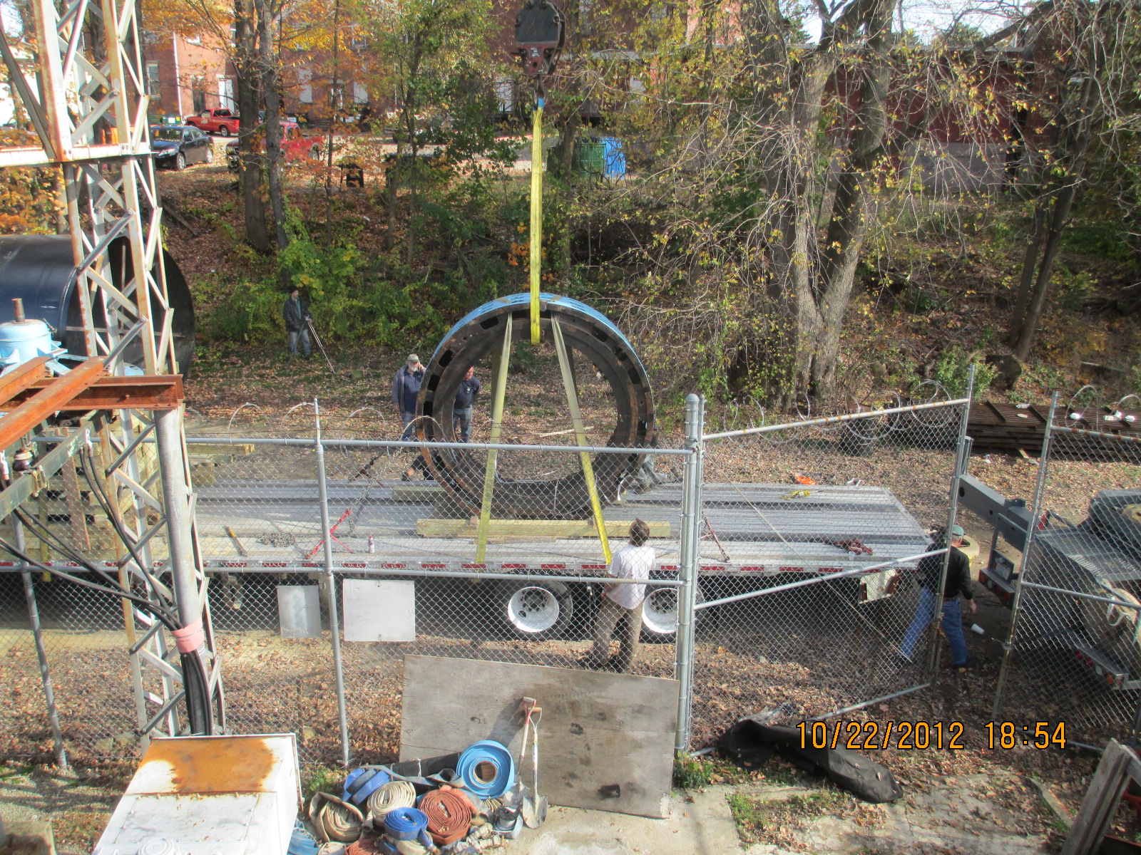
The stator is hanging off the 125 ton crane. We have just installed the chains and binders to hold it in place.
Here we have flown the rotor/headcover/spyder assembly onto the flat bed. Wayne Bailey has been busy giving directions. October 19th, 2012 I am sorry I have neglected all of you!!! I have been crazy busy!!! Please see the following: Indian River Trashrake:
Here I am in New York State, at Jim Besha's, Mechanics Falls, storage yard picking up the pieces of the used Atlas Polar Trashrake.
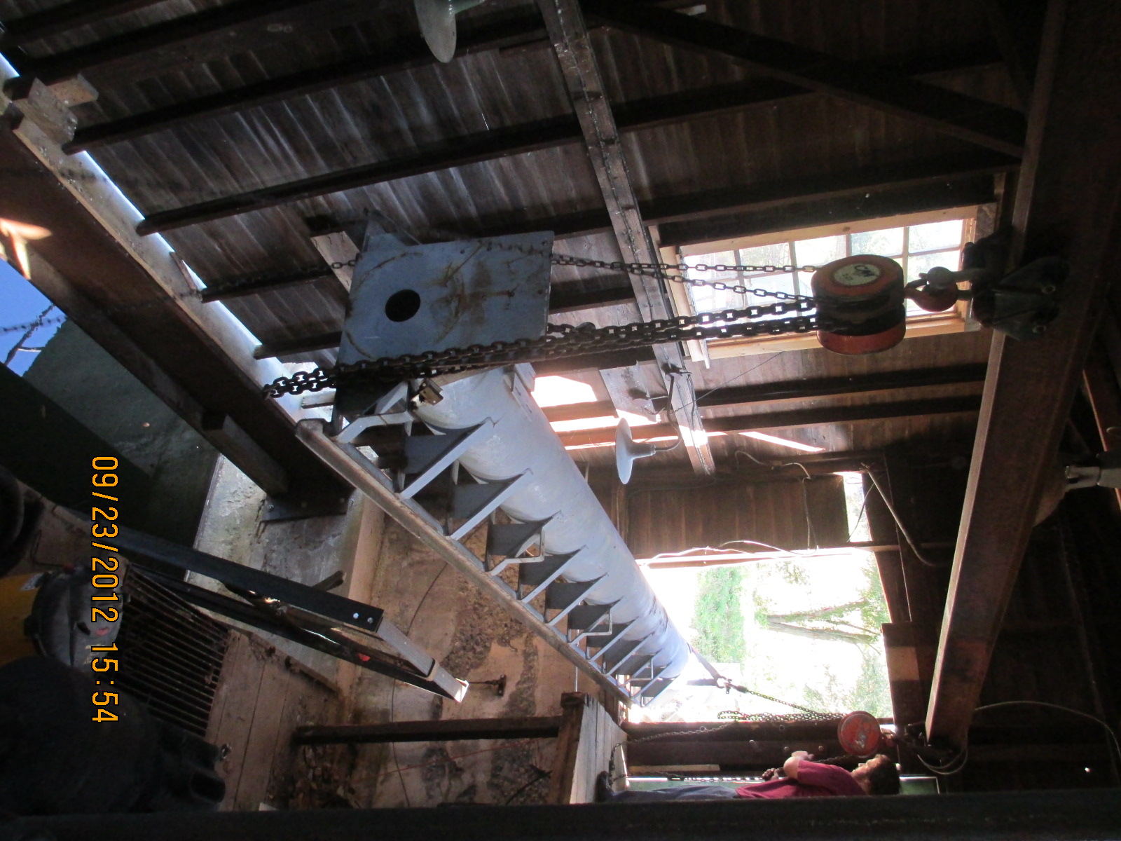
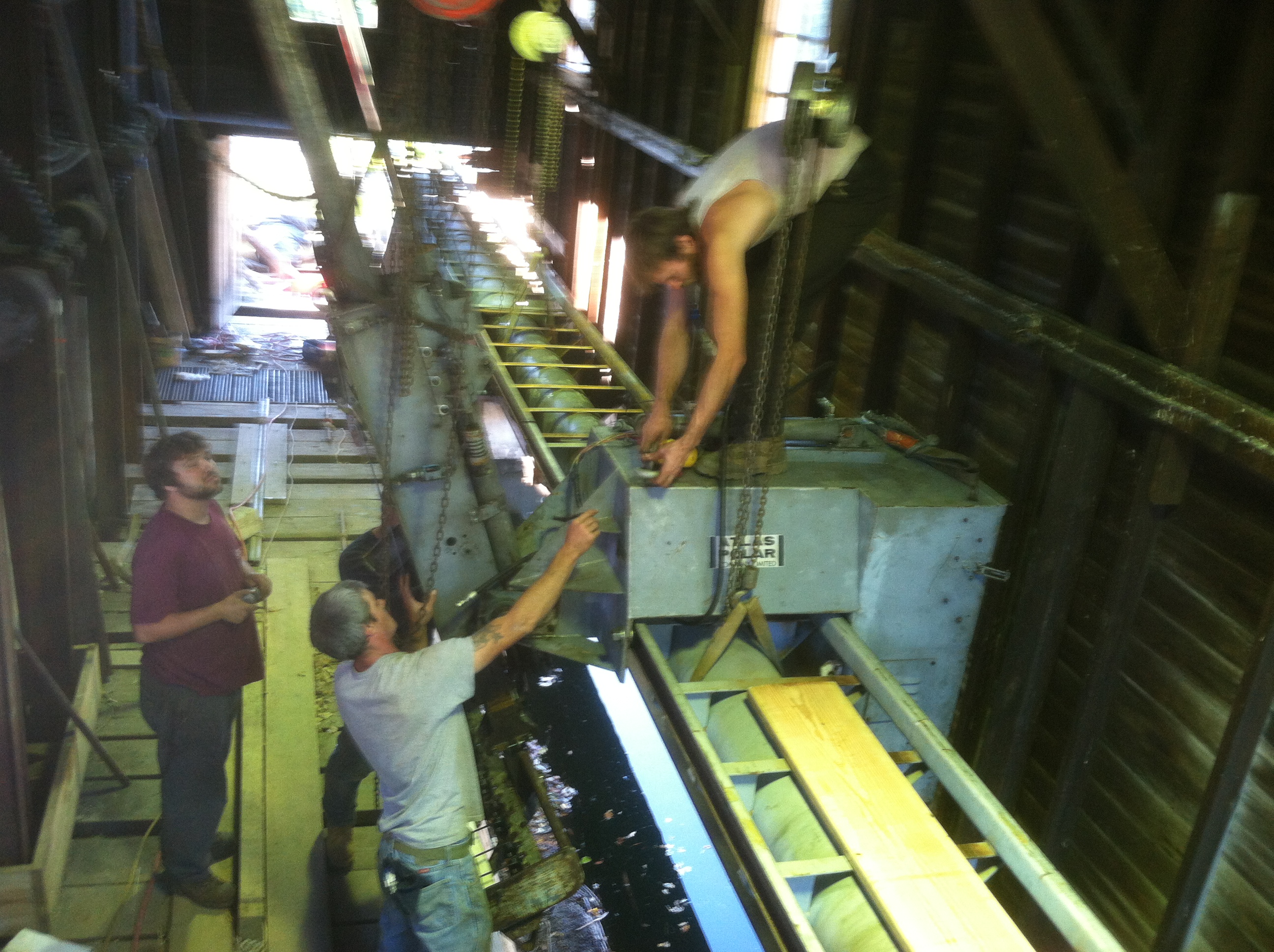
Here we have assembled and rebuilt the rake. We changed out all the cam follower rollers, the hydraulic lines and added a mid span extension to the rail. The roller track was a special channel iron. We had Industrial Steel and Boiler roll us new channel sections. Warren Fay fabricated the center section from a piece of 12 inch pipe. The electrical control boxes were missing. Warren figured out the wiring and the ice cube relays and recreated the control system. In this photo, we are breaking the rake down to load on the trailer to transport it to out Indian River site.
Here we are close quarter rigging the sections of the rake into the Indian River gate house. We used the little front end loader as a crane. It was awkward but got the job done.
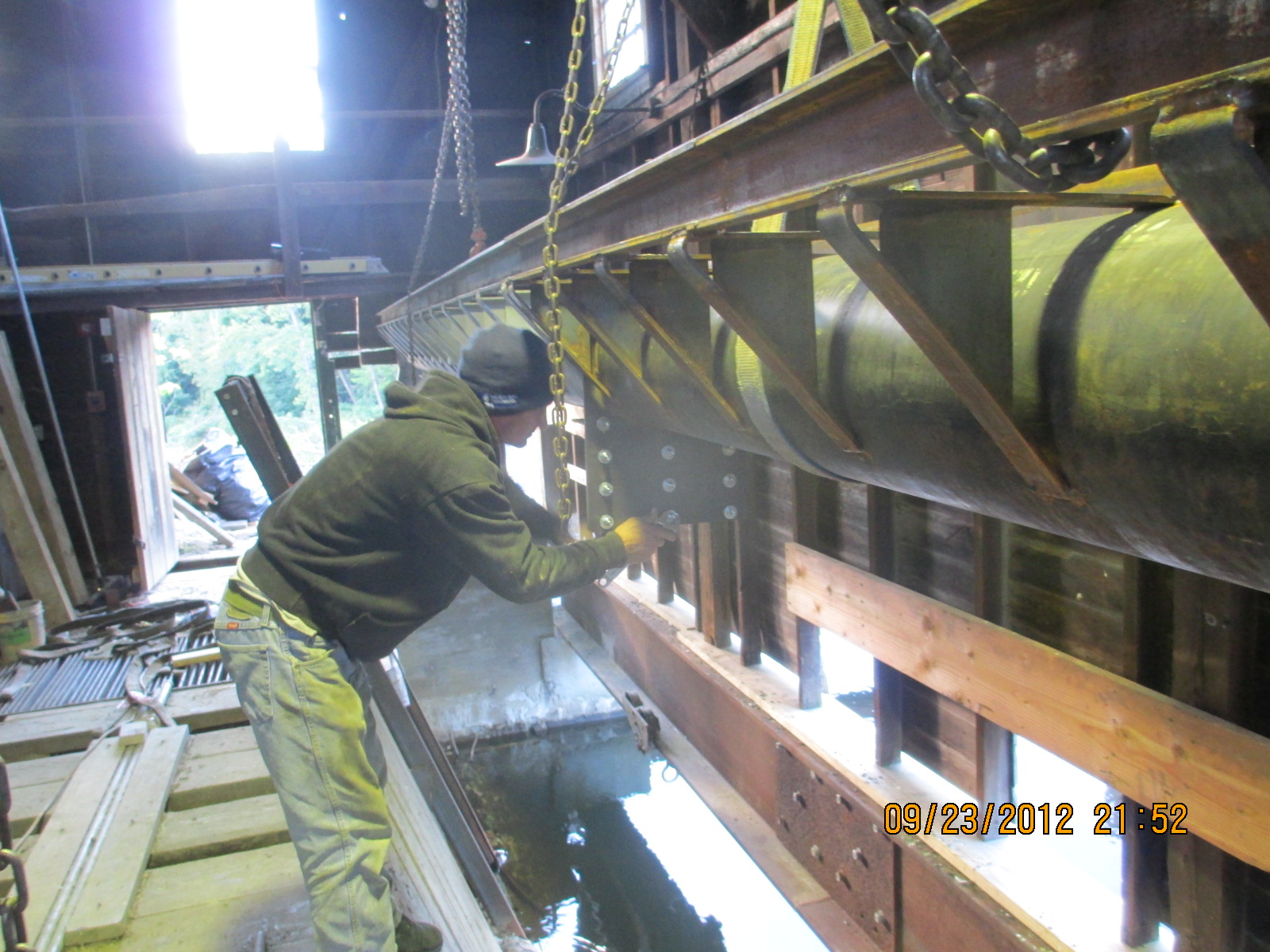
Mike Desrouche is our master rigger. Here he is bolting up the mid span section.
Here we are rigging the rolling control house into the gate house.
Here John Remington, Cole Zub and Mike Desrouche are installing the rake head onto the control house. This rake fit like a glove in the gate house.
Pepperell No. One Generator Disassembly:
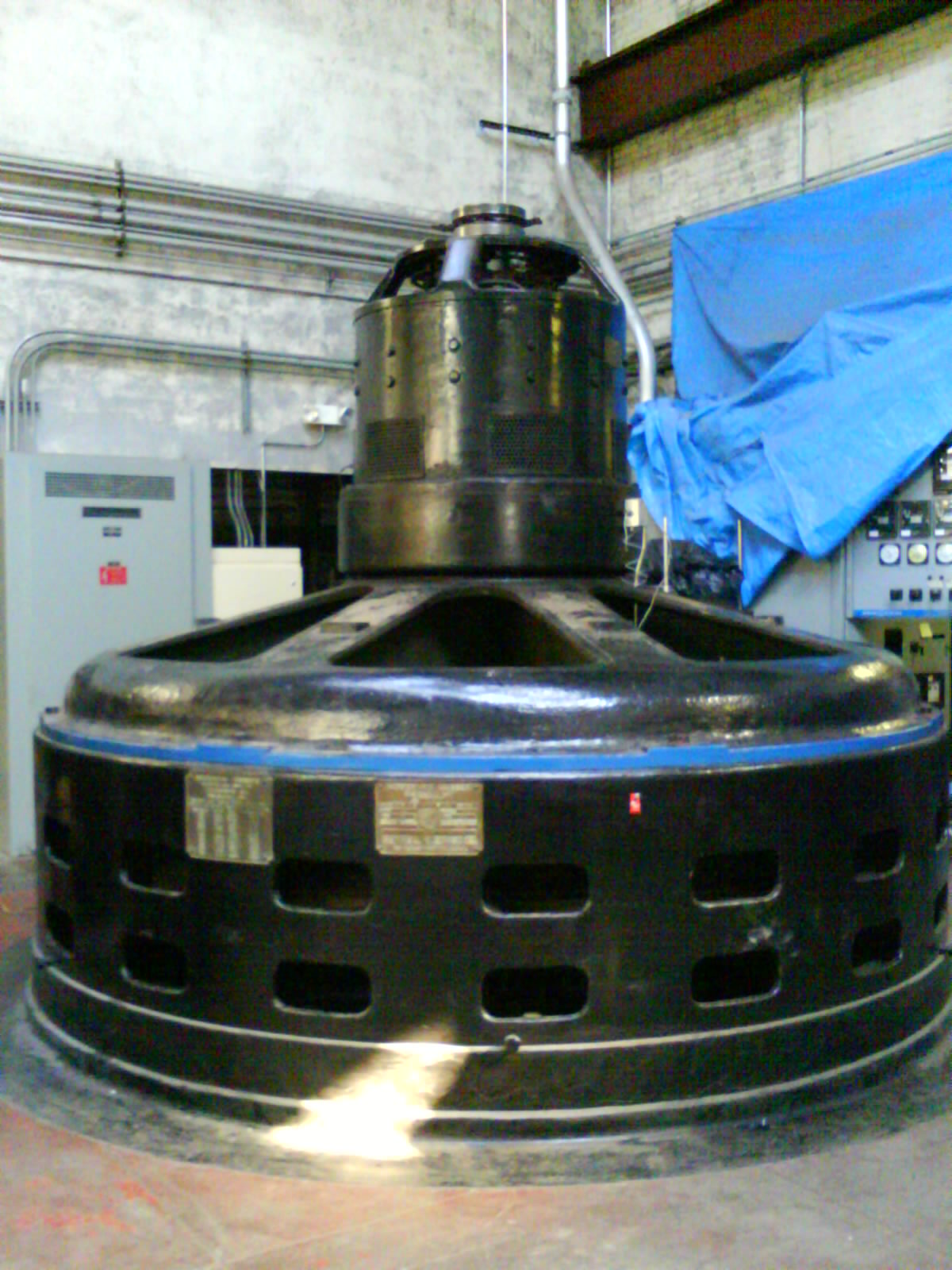
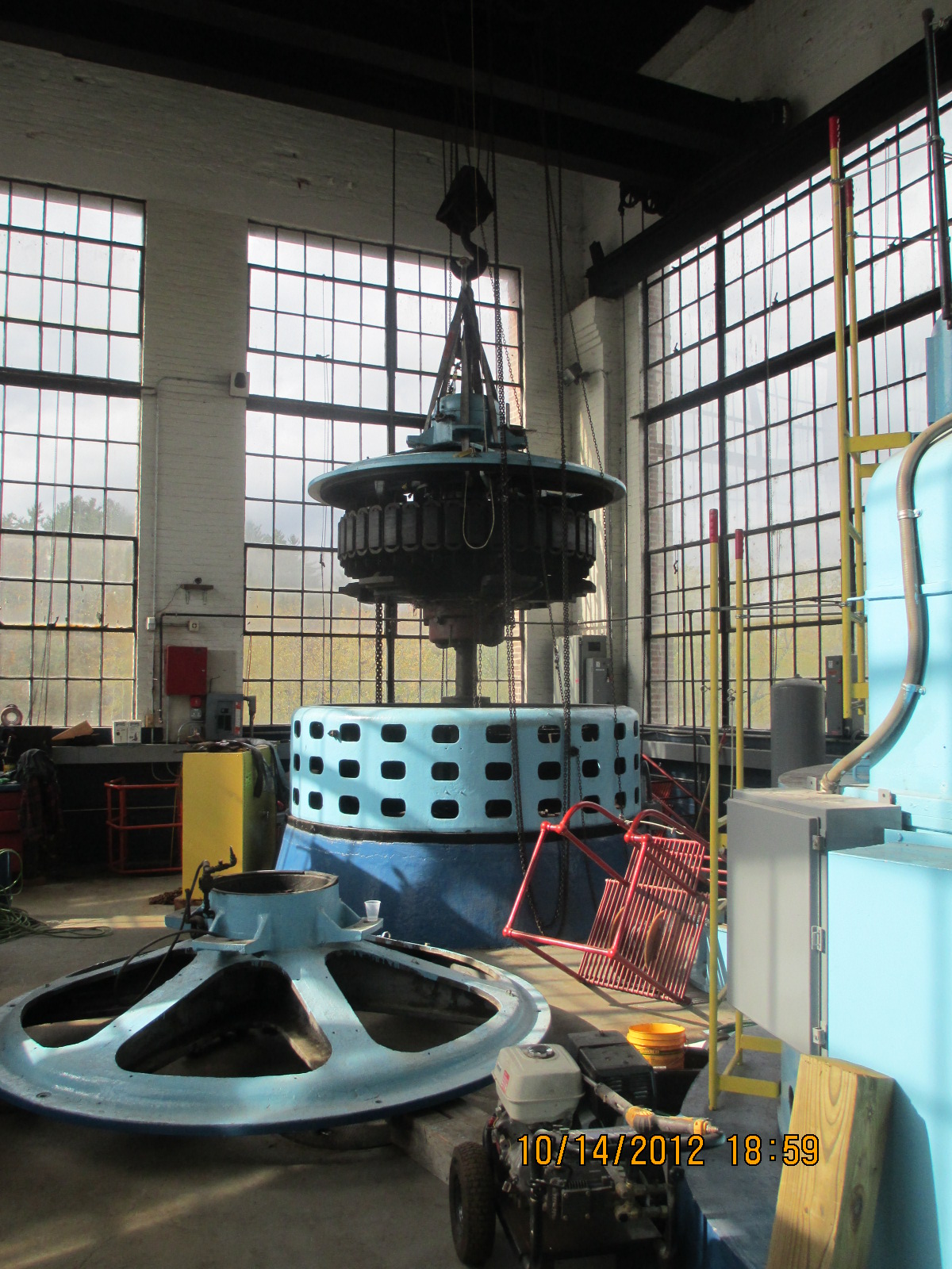
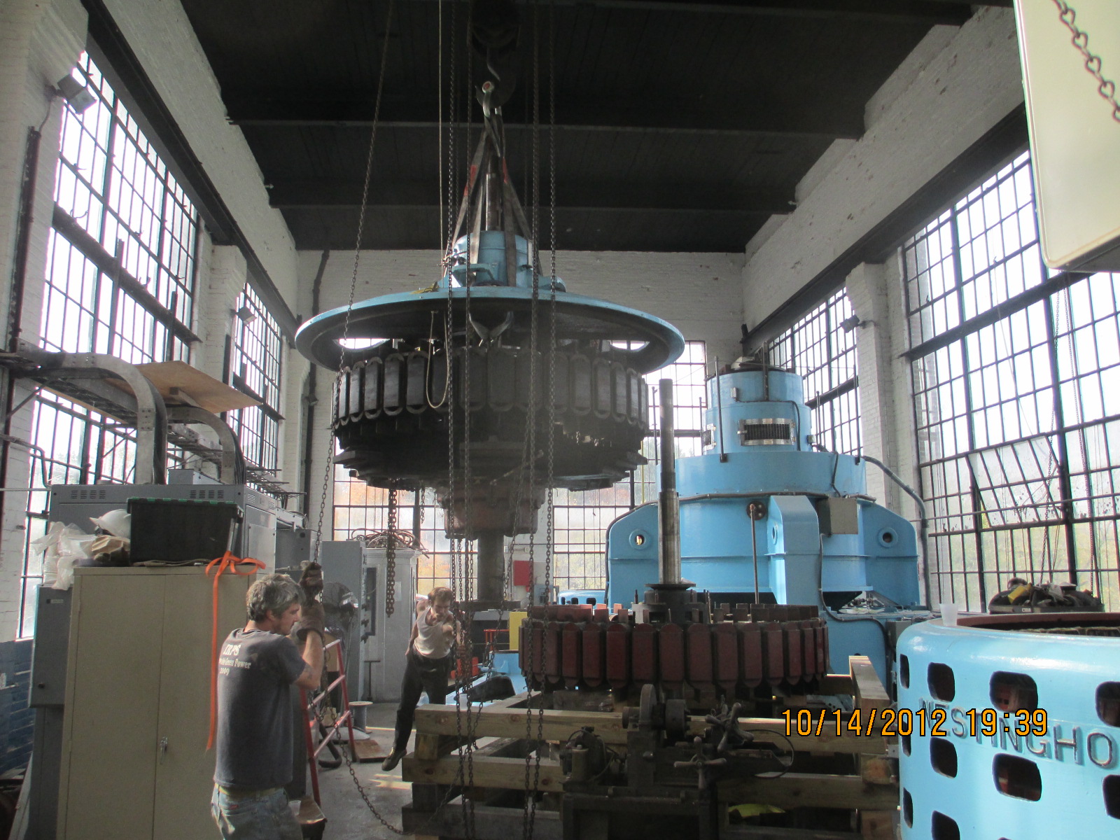
We are sending our No. One generator out to be re-stacked and rewound. We wanted to minimize our disassembly time. We decided to take the rotor, head cover, spyder and bearings as one piece and the stator as the second piece. Here we have lifted the 27,000 pound conglomerate out of the stator.
Here we are flying the assembly through the powerhouse.
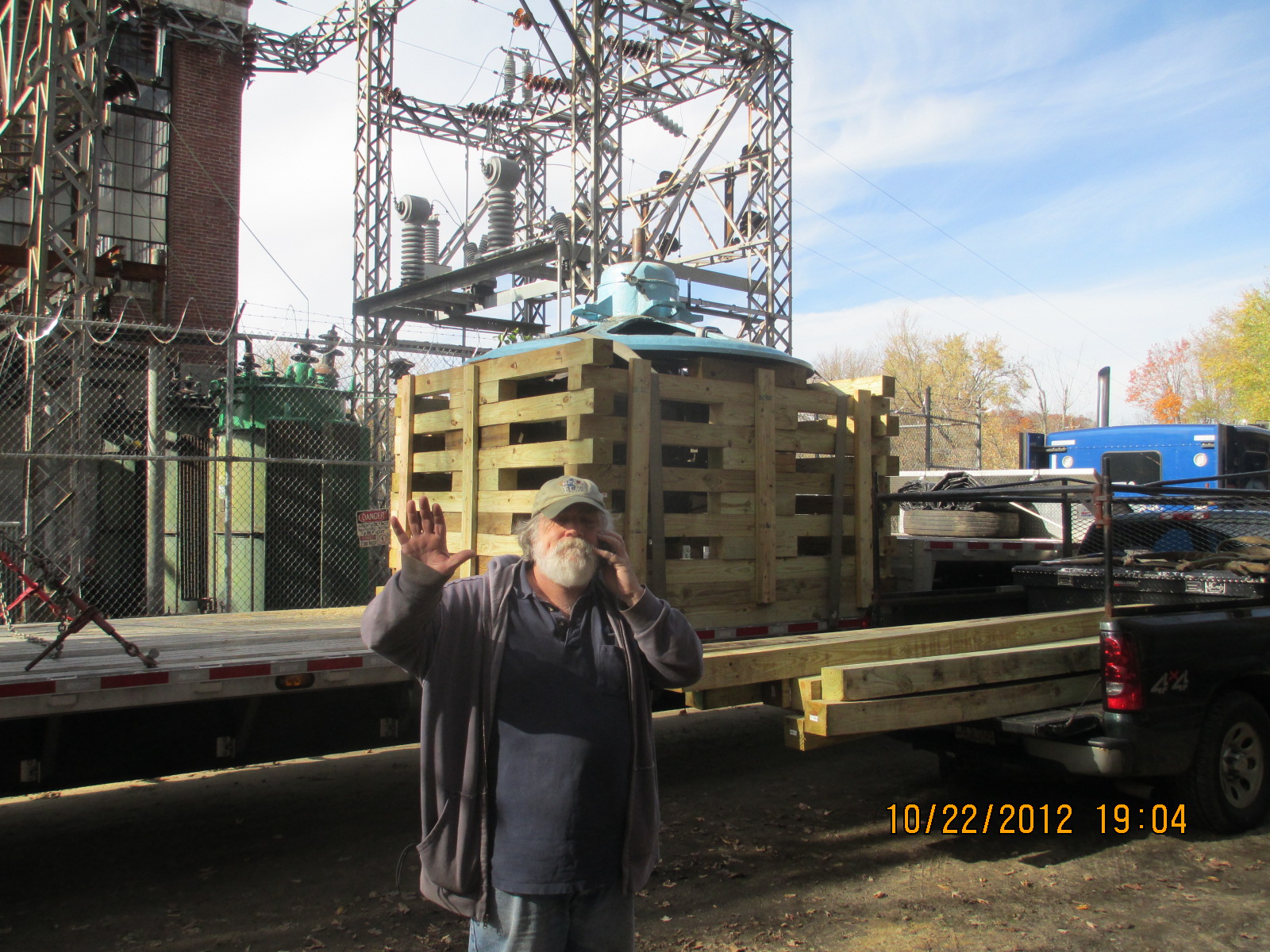
Here we have cribbed up the assembly for shipment on a double drop low boy. We assembled the timbers on top of machinery rollers and lowered the head cover on top the cribbing.
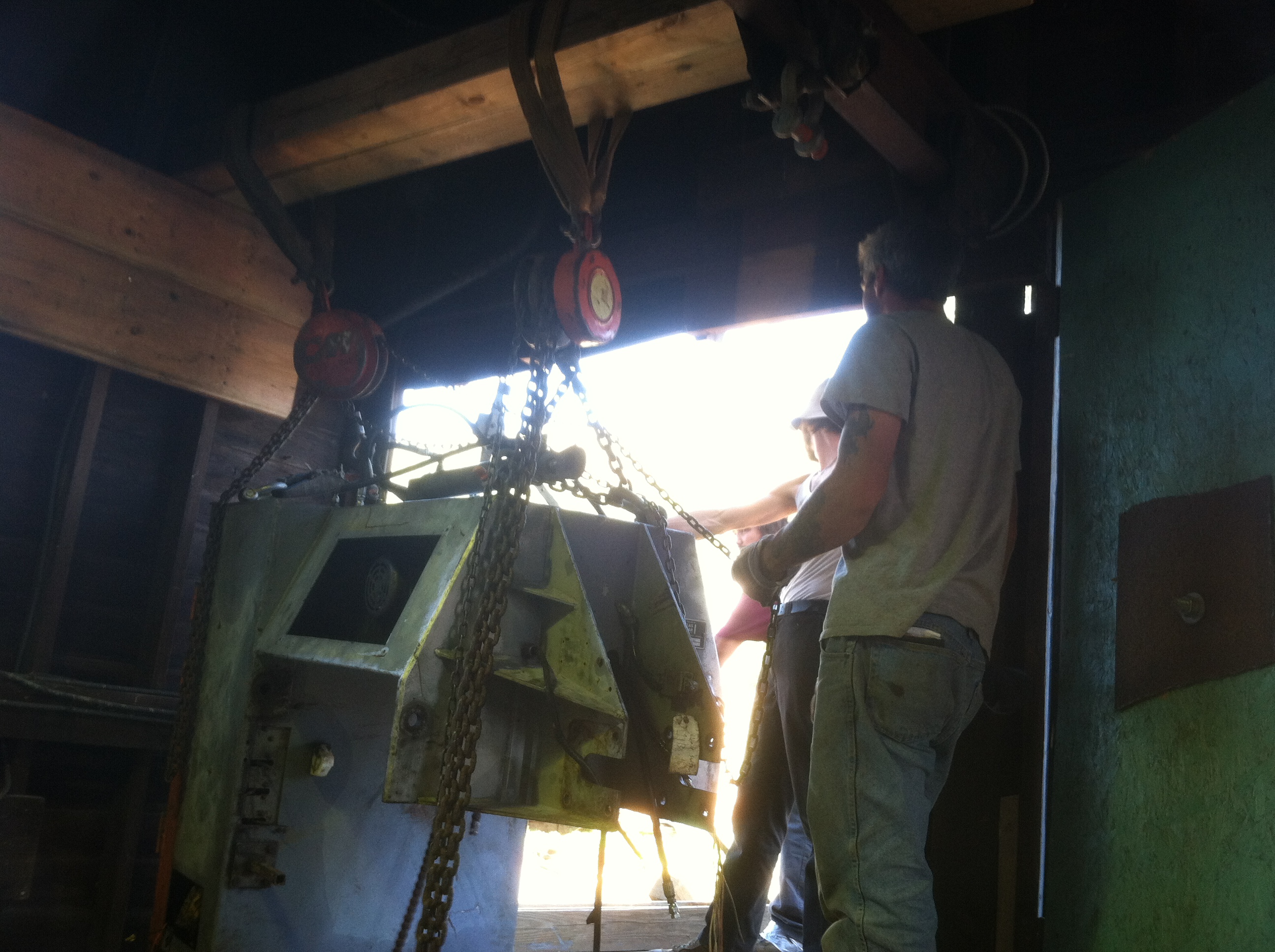
Here we are approaching the doorway.
We had to use the Hilti hammer drill to skim a little concrete off of the door beam to allow the top of the generator shaft to roll beneath the beam.
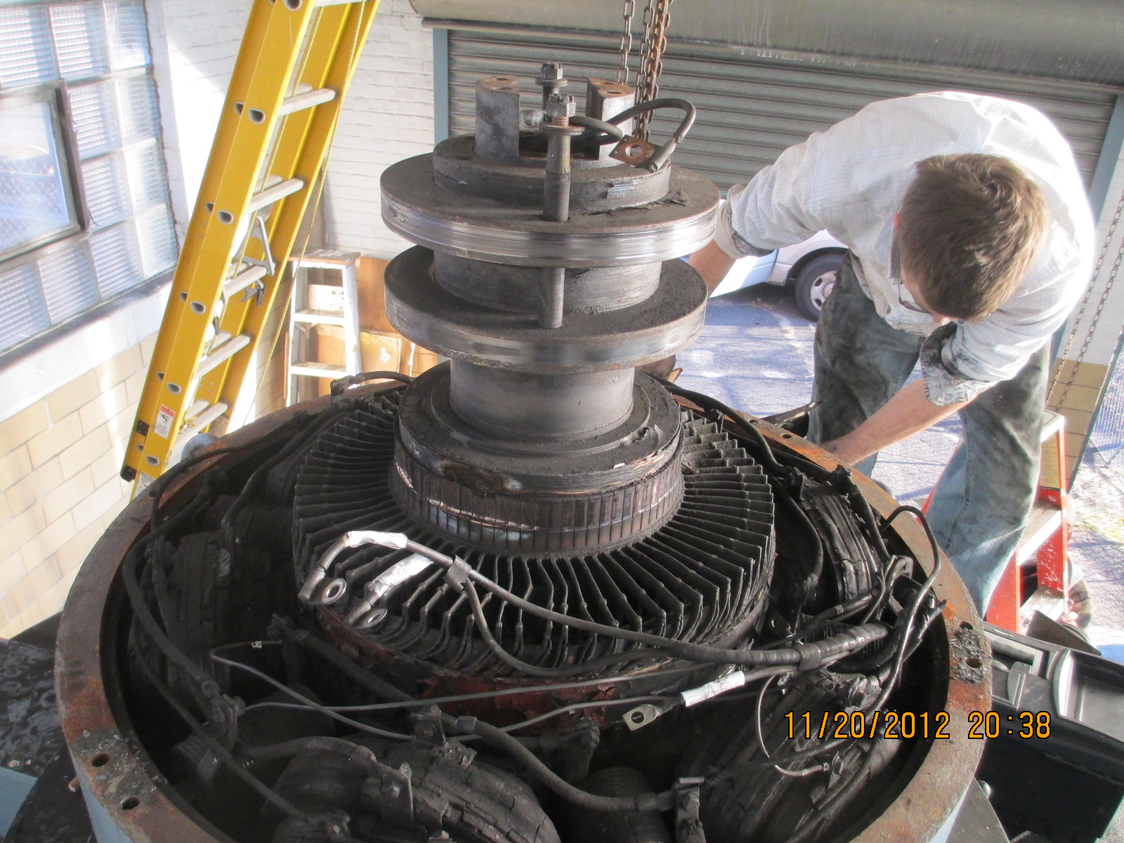
Here the generator is past the door way and is on the porch deck. November 27th, 2012 Our friend Phil Purple could not start his lower TG set. He asked me to come up and help out. He was having trouble with his exciter. One of the 12 volt batteries had gone bad. He replaced it. The unit started up and went on line for a while and then stopped. The switchgear and controls are in a separate building from the TG set. I checked out the wiring and finally concluded that a large DC motor contactor that controls the DC current flowing from the direct connected exciter to the slip rings was not pulling in. I had Phil start the unit rotating. I noticed a horrible clacking noise coming from the top of the GE generator's exciter. It was so loud that it hurt my ears. I climbed up onto the generator and checked the output of the exciter. It had zero voltage. I had him stop the unit so that I could inspect the surface of the copper commutator bars. This is what I found:
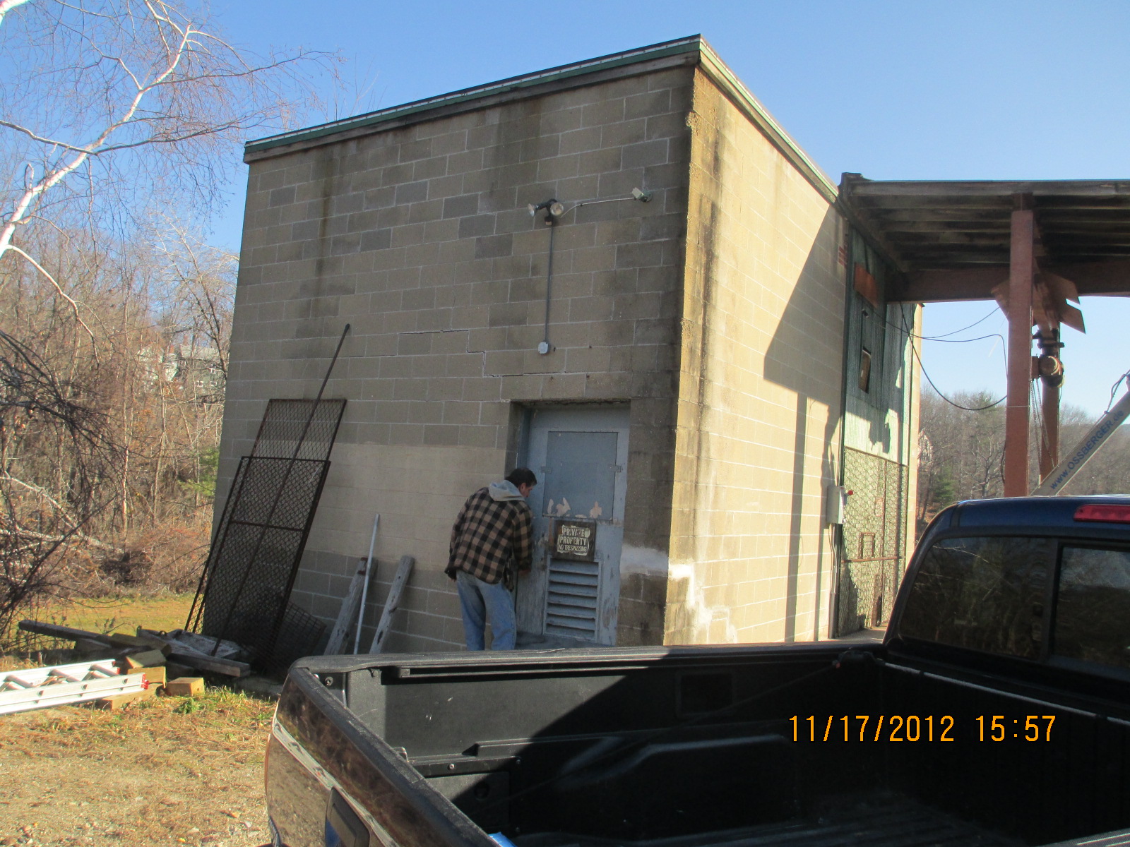
Phil Purple unlocking the door to the former Union Twist Drill Company's lower hydro station.
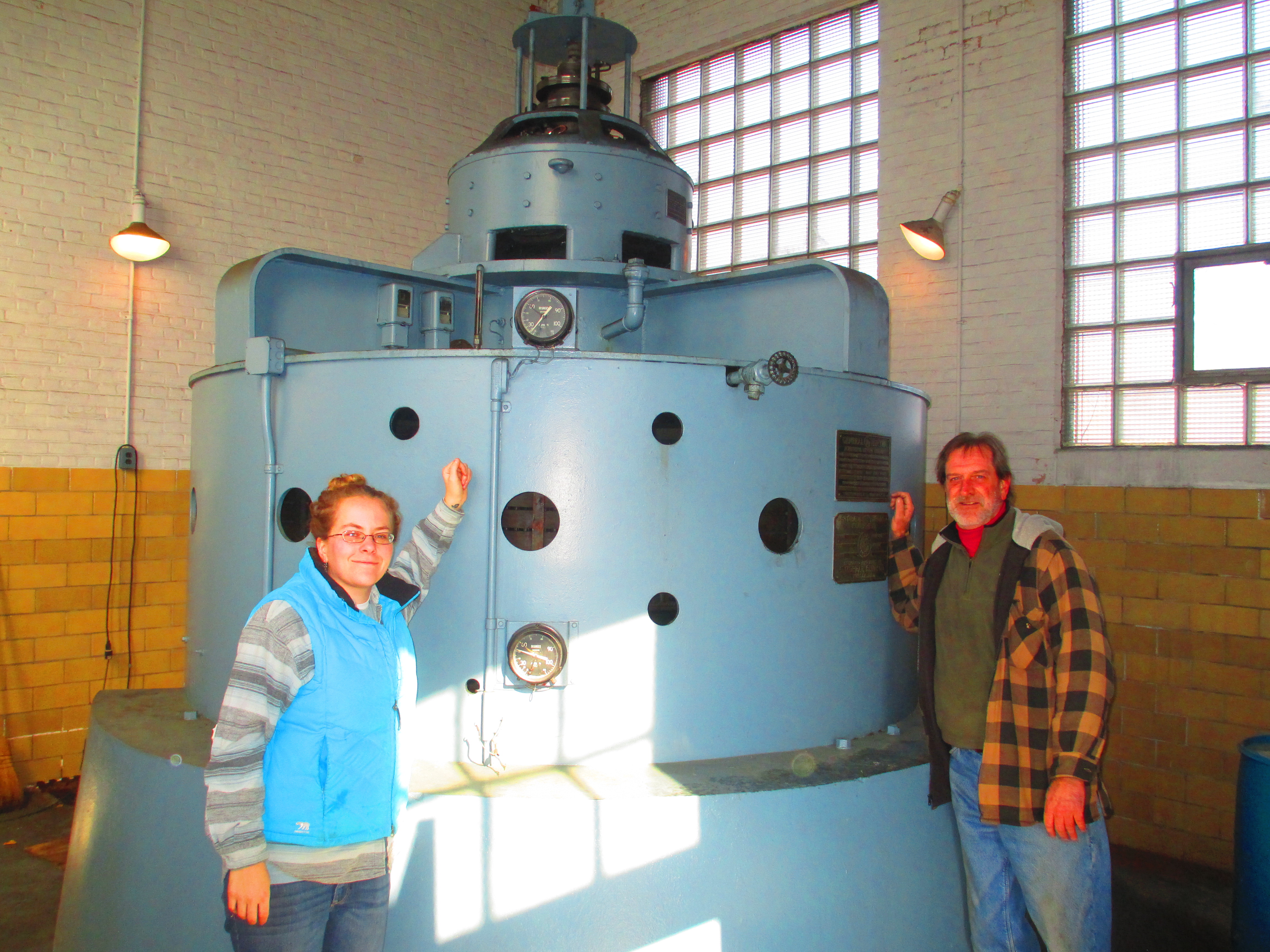
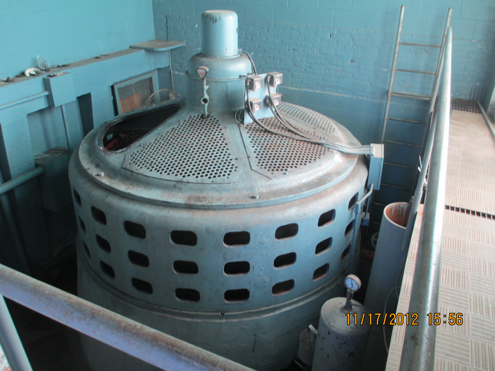
Celesty and Phil in front of the 300 kilowatt, S Morgan Smith Electric Kaplan. This unit is unique in that the Kaplan turbine blades are actuated by a pair of Selsyn motors instead of a hydraulic cylinder. This unit has been in continuous operation for 65 years.
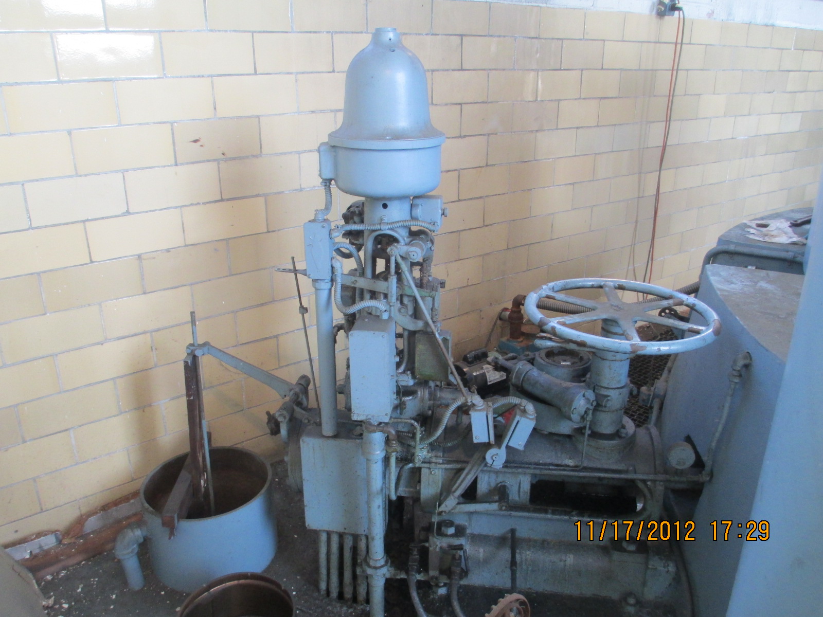
A view of the Kaplan's Woodward governor. Note the pond level float control directly connected to the governor.
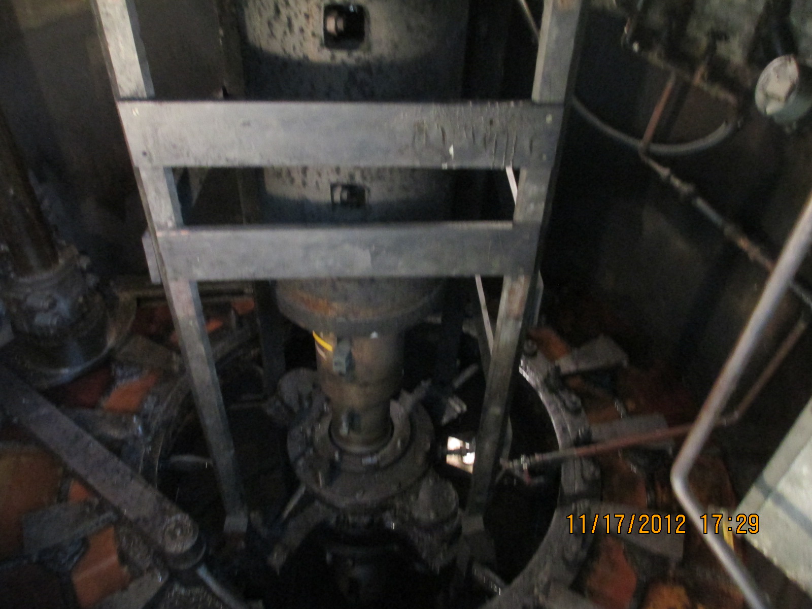
A view of the turbine head cover. Note the wicket gate control bell cranks, heavy duty shift arms and massive quarter block assembly for the lignum vitae wooden bearings. The large cylindrical coupling being guarded by the wooden frames contains the actuator Selsyn motor.
Will Fay has removed the brush holder and cast iron frame from the top of the exciter. Note the damage to the copper commutator bars and the horrendous cracking of the stator coil insulation.
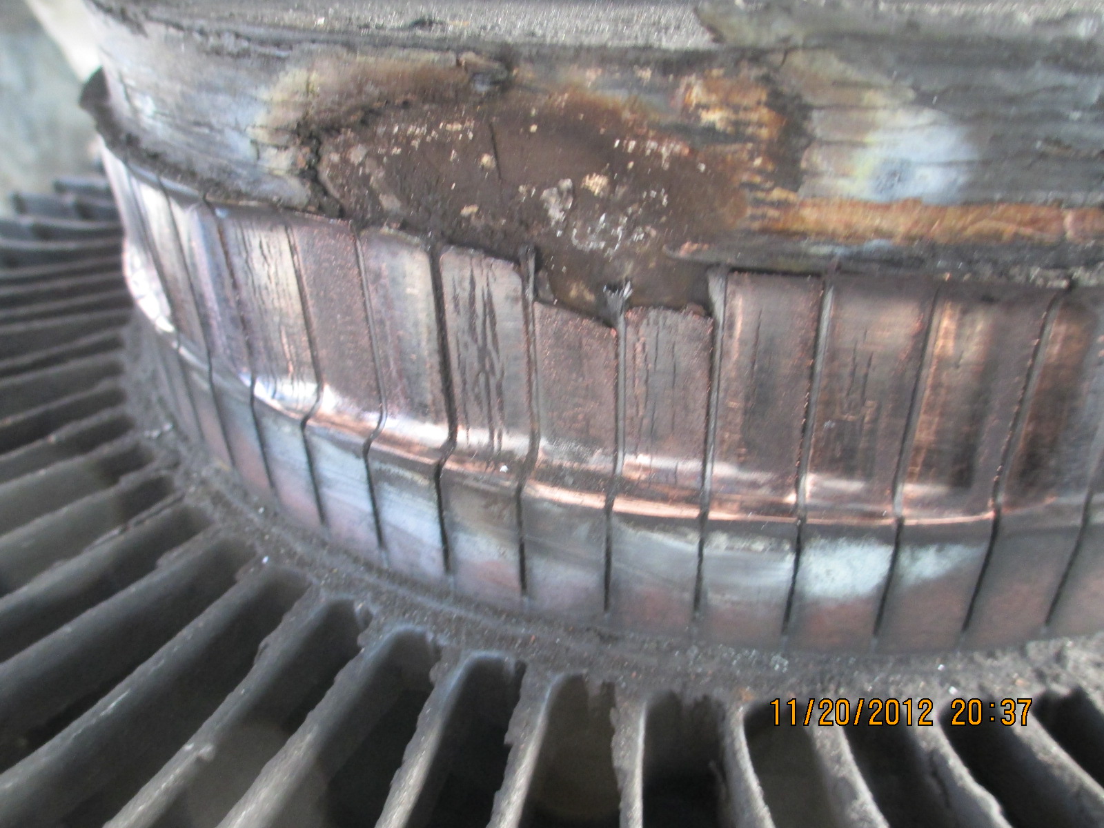
A close up of the damage to the commutator. The horrible clacking noise that I was hearing were the brushes dropping into this hole and than being lifted out 180 times in a minute. This unit was very close to either catching on fire or electrocuting someone. Now Will and I need to figure out how the rotor is attached.
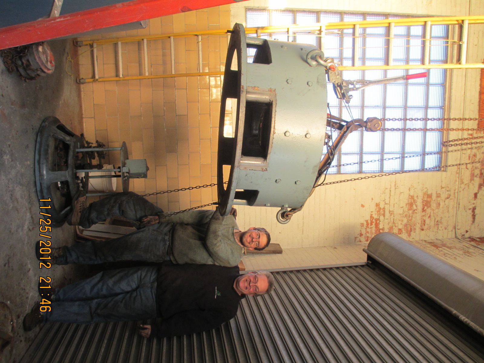
Here, Will and I have rigged the stator from the top of the generator down to the floor.
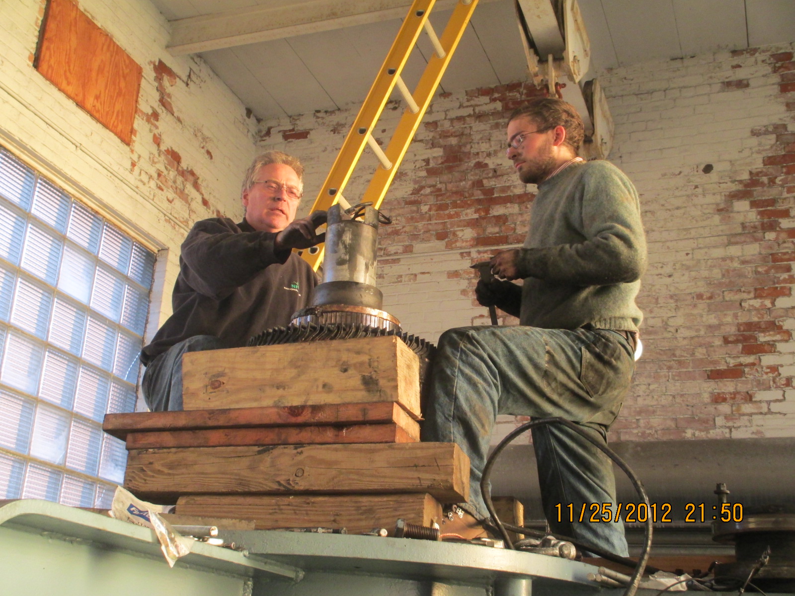
Here we have determined that the shaft on top is not an extension of the generator shaft. The wires sticking out the top conduct the DC current to the rotor coils to create the magnets that revolve on the flywheel. We determined that the bottom of this shaft is flared out and cupped. The rotor is pressed down onto the top of the main shaft. The hole is 3 inches in diameter and it is 22 inches down to the top of the generator shaft. We are having Warren make us a jacking pole from a piece of 3 inch bar stock. He will turn the OD down by 100 thousands and bore a 3/4 inch hole through the stock. We will drop the bar down over the wires until it bears against the generator shaft with the exciter wires safely inside the jacking pole. We will set the 30 ton Porta Power cylinder on top of the jacking pole. We will put a strong back across top of the cylinder and run 5/8 inch threaded rod down to the 5/8 tapped holes in the top of the shaft. We can then pull the exciter rotor by jacking down on the shaft while the threaded rods pull up on the rotor. I will take more pictures!!
This is the upper unit at Phil's upper site. It is an S Morgan Smith Francis machine.
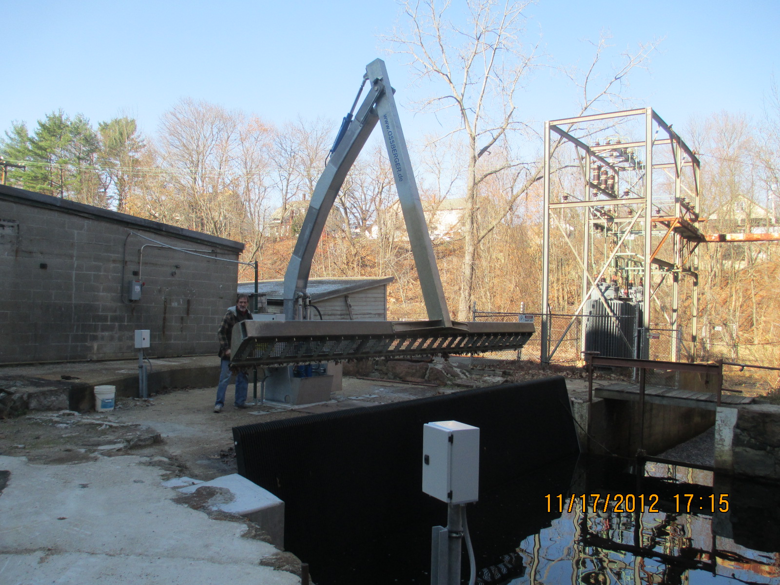
This is the new Ossberger trashrake with new plastic trash racks that clean the lower site's racks. Note that it cleans the whole rack at one sweep. The plastic racks are supposed to be excellent for preventing frazil ice build up.
|
|
|