GREEN                           

     AND

        CLEAN

             POWER        

French River Land Company's Website!


French River Land Company's Home Page!

Poetry of Power

FRL History

Hydrolec Disassembly

Hydrolec Rebuild

Key Personnel

Machine Shop

News Page

Previous Pictures

Previous Pictures Two

Previous Pictures Three

Projects

For Sale

HYDROELECTRIC SITES:

Alternatives Hydro

Anasagunticook Lake Dam Replacement-    C.Fay & W.Fay

Appleton HEP-     Jim Lichoulas

Badger Pond Dam Removal

Senor Bonifettis' sites in Chile

Buttermilk Hydro

Chittendon Falls

Claytor Dam

Collins Bascule Dam

ESAC WORKS      July 1985

Fiske Mill

1852 Fourneyron

Golden Pond Hydro

Hunts Pond

Jaffery Fire Protection

Konkapot Creek

Lake May Pelton Wheel Removal

Livermore Falls

Martinsville Hydro

OSV

Shaker Mill Dam

Silk Knitters- Ron Macleod

South Village Dam

Sparhawk Mills

Tannery Pond

Turners Falls Generator Rewind

Valatie Falls

Valley Paper

USEFUL ENGINEERING:

Air Admission to Hydro Runners

The Banki Water Turbine Mockmoore and Merryfield

Barrel Stave Bearing Repair

Bishops Method- STABGM Program

Blade Pitting- Boving LTD 1930

Cavitation- Accelerated Research, Allis Chalmers Research

Cavitation & Vibration of a Draft Tube

Cavitation- Prevention & Reduction, Allis Chalmers Research

Causes & Effects of Cavitation in Hydraulic Turbines

Chain Turbine by: Nguyen Minh Duy

Chain Turbine Mechanics- Discussions with Duy

Characteristics of Modern Hydraulic Turbines-Chester Larner

Comparative Tests On Experimental Draft Tubes- C M Allen & I A Winter  1923

Design of an Overshot Waterwheel

(by Carl Weidner)

Design of Pelton Buckets

Design of Small Water Turbines for Farm and Small Communities

Design of the runner of a Kaplan turbine for small hydroelectric power plants: Timo Flaspöhler

Draft Tube Design

Draft Tubes of Hydro-Electric Stations by M. F. Gubin

Draft Tube Tests

Ejection into Tailraces of Hydropower Plants: S. M. Slisskii

Fall Increaser- Henry Ford

Fall Increaser Herschel Venturi Tube

Fall Increaser Moody Ejector Turbine

Fall Increaser Hydraulic Jump Apron

Feasibility Studies for Small Scale Hydropower Additions, A Guide Manual, US Army CORPS of Engineers

Flashboard Pins

Gatecase Design- Kovalev

Governor Theory for the Plant Operator

Graphics of Water Wheels- William Fox

Hydraulic Motors- M. Bresse & F. A. Mahan 1869

Hydraulic Turbines- Robert Long Daugherty

Hydraulic Turbines by Arnold Pfau

Hydraulic Turbines Gelpke & Van Cleve

Hydrokinetic Energy in Massachusetts- William D. B. Fay

Hydrostatic Beam Analysis

Impulse Turbines  by Ely Hutchinson

Kaplan Blade Design NACA Air Foil- Report No. 460

Kaplan Blade Design NACA Air Foil- Report No. 628

Kaplan Design- Kovalev

Kaplan Design Marko Kogovsek.xls

A Laboratory Study to Improve the Efficiency of Crossflow Turbines- N. Aziz & V. Desai

Meggering Generators

Meggering      Earth Resistance

Motors as Generators for Microhydro, Nigel Smith

Operation & Maintenance of Hydro-Generators

Out Gassing of Cross Flow Turbines

Parallel Operation of Turbines Analysis

Pelton Design- Daugherty

Powerhouse Design- Miniwatt Hydro

Powerhouse Design- Natick Dam

Power Plant Inspection

Rake-Leonard

Rake-Newport News

Rack Design-Chicopee-Olav Hotvedt

Rack Design- PHI- Bill Fay

Rack Design-PHI-Brian French

Rack Design-PHI-Ken Smith

Rack Design-ASCE

Rack Design- Hydraulic Institue of Munich

Rack Design-Flow Induced Vibrations

Selecting Hydraulic Reaction Turbines BUREC

Shafts- Kovalev

Shaft Couplings

Snows Improved Water Wheel Governor

Standard for Hydraulic Turbine and Generator Shaft Couplings and Shaft Runout Tolerances

Stoplog Design Calculation

Stoplog Structure Design Calculation

Stress Analysis of Hydraulic Turbine Parts, BUREC- F.O. Ruud

Some Fluid Flow Characteristics of a Cross Flow Type Hydraulic Turbine- Durgin & Fay

Tenth Census of the US, 1880, Water Power of the US, Part I- Professor Trowbridge

Tenth Census of the US, 1880, Water Power of the US, Part II- Professor Trowbridge

Tests on a Kaplan Hydraulic Turbine

Theoretical Conditions Related to an Open Channel Flow Linear Turbine- Ishida & Service

Theory of Turbines- De Volson Wood

Treatise relative to the Testing of Water-Wheels and Machinery, James Emerson 1879

Turbine Water-Wheel Tests- Robert Horton

Turgo, A High Speed Impulse Turbine- Paul Wilson

Vortices at Intakes

Water Hammer-Lorenzo Allievi-Text

Water Hammer-Lorenzo Allievi-Figures

Water Hammer-ASME Symposium 1933

Water Hammer _ Norman Gibson

Water Hammer-E.B.Strowger

Waterpower Engineering-Daniel Webster Mead

Water Wheel Design- Ken Smith

Weights

WHAMO

Wooden Penstocks

TRADE CATALOUGES:

Bradway Turbine  (progressive gate)

Brook Waterwheel

Charmilles Turbines

Christiana Machine (register gate)

Dayton Globe

Electric Machinery Company (EM)

English Pelton

ESAC

Essex Turbines

GE WW Vert Gen

GE Springbed Brg

Gilkes Turbines

GilkesWaterpower

Head Gate Hoists- S. Morgan Smith

Holyoke Hercules

Hunt Cat 29 A&B

Hunt cylinder

J & W Jolly       (cylinder gate)

Kingsbury  Brg

Leffel Bulletin 38

Leffel Bulletin 54

Leffel Hoppes Unit

Leffel Laboratory Unit

Leffel Miscellaneous

Lombard Direct-Connected Oil Pressure Governors Bulletin N0. 113 October 1st, 1912

Lombard Governor

Lombard Governor Company Type T Instruction Book

Lombard Governors for Waterwheels and Steam Engines-1902

Lombard Water Wheel Governors Catalouge 26

Pelton Wheel (1909)

Pelton Wheel (1925)

Ridgway Perfection Water-Wheel

Rodney Hunt

Samson PamK

Smith Bulletin 110

Smith Power Tables

Smith Kaplan

Smith Power

Smith Pelton

Smith Develop

Smith Turbines: Bulletin 105

Swain Turbine

Trump Hydraulic Turbines

Trump Turbines

Tyler Turbine

Vertical Shaft Water Wheel Driven Generators- General Electric

Wellman Seaver Morgan

Westinghouse Small Vertical Waterwheel-Driven A-C Generators, July 1944

Westinghouse WW Generators

Woodward Governor


Links:

Swiftriverhydro.com

damengineers.com

Smith Alternative Energy (www.smithtest.com)


TANNERY POND PAGE   

The facility is licensed by the Federal Energy Regulatory Commission. It is known as Tannery Pond Hydro, FERC L.P. No. 8895-MA .  The project is located on the Millers River in Winchendon, Massachusetts. It consists of an existing 248 foot long by 10 foot high, concrete capped, masonry gravity dam founded on ledge. The crest of the spillway is at 936.95 NGVD. The left, southerly abutment consists of a concrete, monolith pinned to the ledge. A series of cast iron brackets spaced at 6 foot intervals supports 30 inches of flashboards and an access catwalk. The top of the flashboards is at 939.45 NGVD. The right, northerly abutment contains a 10 foot wide by 8 foot tall flood gate. The gate is operated vertically by a back geared Rodney Hunt gate stand. The dam impounds Tannery Pond which has a surface area of 9 acres with a storage capacity of 47 acre-feet and a normal surface water elevation of 939.45 feet NGVD.

 A reinforced concrete, 34 foot long by 16 foot wide powerhouse is located adjacent to the northerly dam abutment. A short forebay with a stoplog structure and trash racks leads into the waterbox. The waterbox contains two hydraulic turbines, which discharge vertically beneath the powerhouse. A 25 foot wide by 425 foot long tailrace conveys the water back to the Millers River. The powerhouse is interconnected to the 13,800 volt, Massachusetts Electric Company's distribution line on River Road. A short, 125 foot long, transmission line runs from the road to a wooden pole adjacent to the power house. An air break switch on top of the pole controls the flow of power from the arial line to a 6 inch conduit which is attached to the pole and is buried beneath the parking lot. The conduit then runs to a 13,800 to 480 volt station transformer. 

The powerhouse contains two turbine/generator units with a total installed capacity of 189 kilowatts. 

A) Unit Number One: Rodney Hunt Francis turbine.

 It is a model Type 80, Hi Test unit with airfoil adjustable wicket gates, at 14 feet it produces 142 horsepower, Rodney Hunt Francis turbine

It is a model Type 80, Hi Test unit with airfoil adjustable wicket gates, at 14 feet it produces 142 horsepower, rotates at 184 rpm, has a hydraulic capacity of 105 cfs and will make approximately 97 kilowatts at the generator leads. 

B) Turbine Two- Leroy Somers Tube turbine

It is a model Hi H automatically adjustable semi Kaplan which at 14 feet net head produces a maximum output of 96 kilowatts while consuming 122 cfs and can regulate down to a minimum of 31.5 kilowatts while consuming 49.4 cfs.

The station hydraulic capacity would be 227 cfs which occurs approximately 15 % of the time.

The lead machine would be the Semi Kaplan which would operate between 49.4 cfs which occurs approximately 60 % of the time and 122 cfs which occurs 22 % of the time.

The lag machine would be the Francis machine which would operate up to the combined hydraulic capacity of 227 cfs at 15 % of the time.

This plant is currently interconnected with the Massachusetts Electric Company. An interconnection study was conducted by Mas. Electric and the metering and telephone poles were installed and paid for by French River Land Company. The metering and protective relays have been calibrated every year since the date of installation.

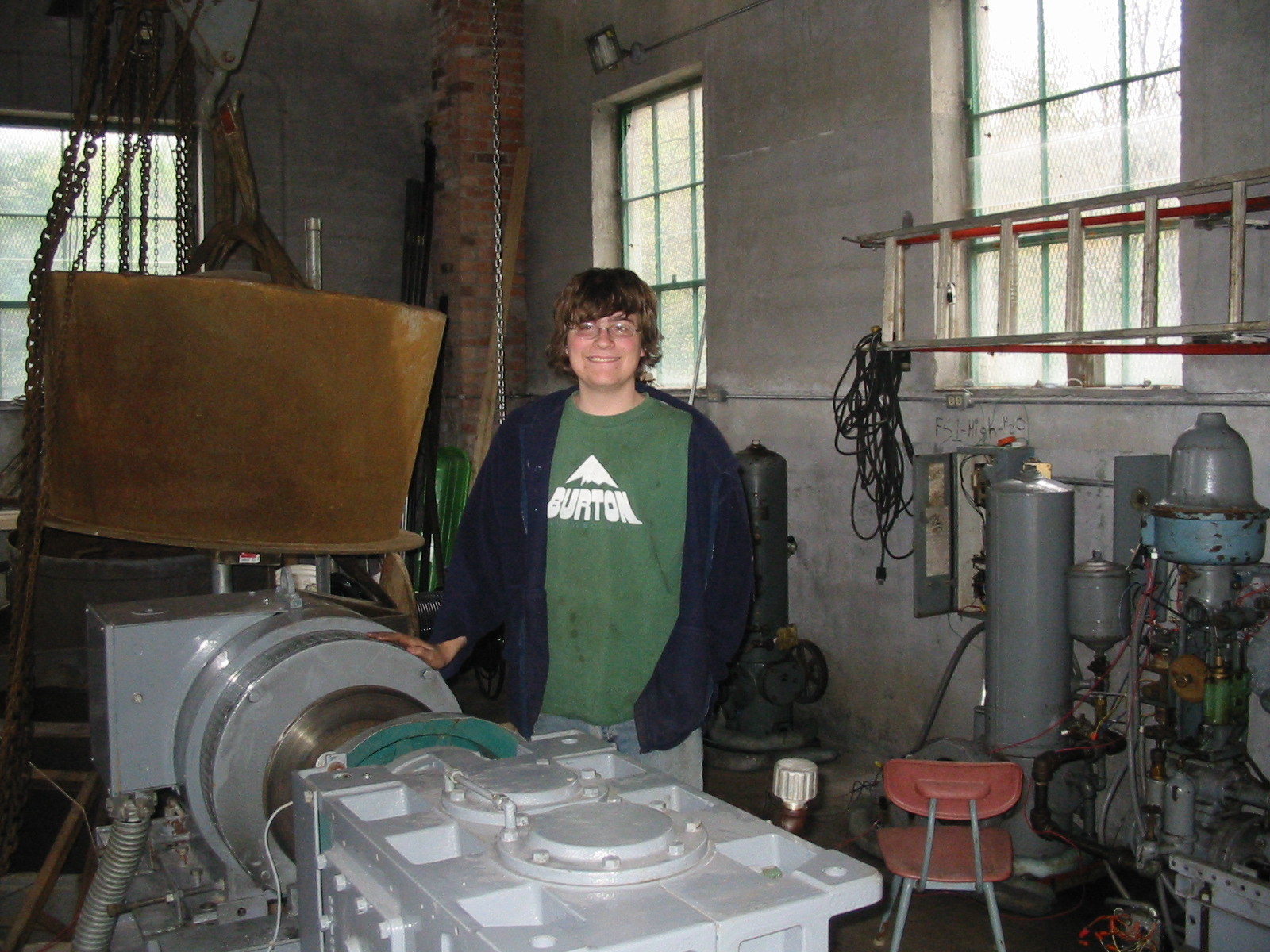
    Tannery Pond Hydro was re-activated in the spring of 2004. The basic equipment was installed in 1998 but the site was never completed for commercial operation. Celeste, Will, Warren and Bill Fay aligned the generator and gearbox, installed a tachometer controlled relay, a disc brake on the high speed generator shaft, debugged the control system and commenced operations in late May of 2004, just in time to miss the Spring runoff. Bill Munch designed the original control package and did much of the work of de-bugging it.

Will Fay inspecting the new disc brake on Unit One. Note Woodward governor and pump in background.


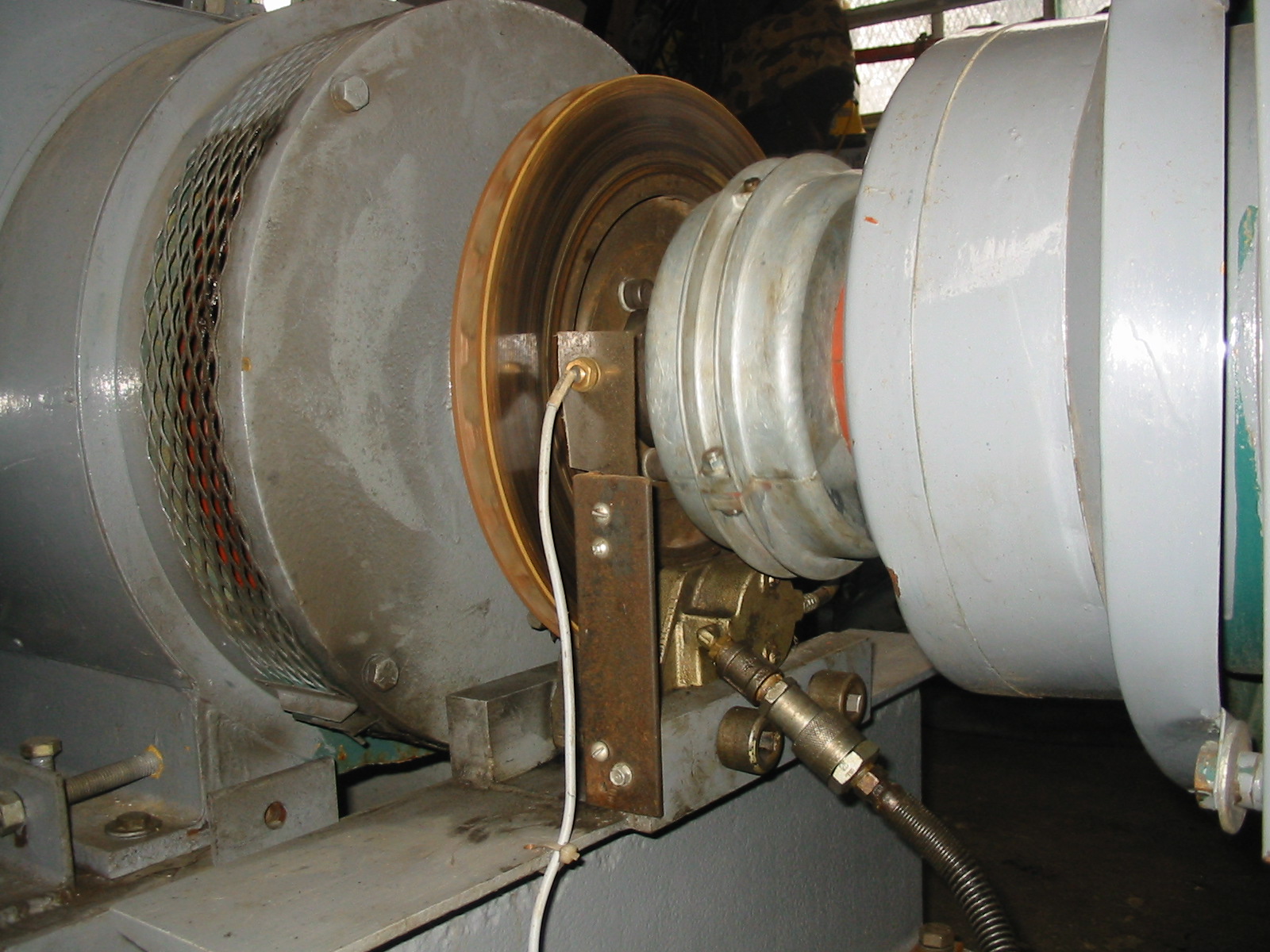
Close up of the new disc brake

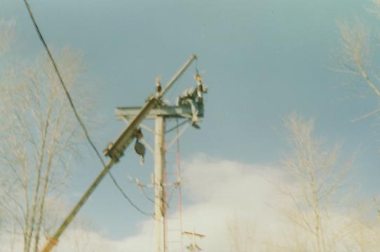
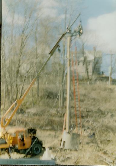
Installation of 22,500 volt air break switch.

Bad picture of welding on top of 40 foot pole.

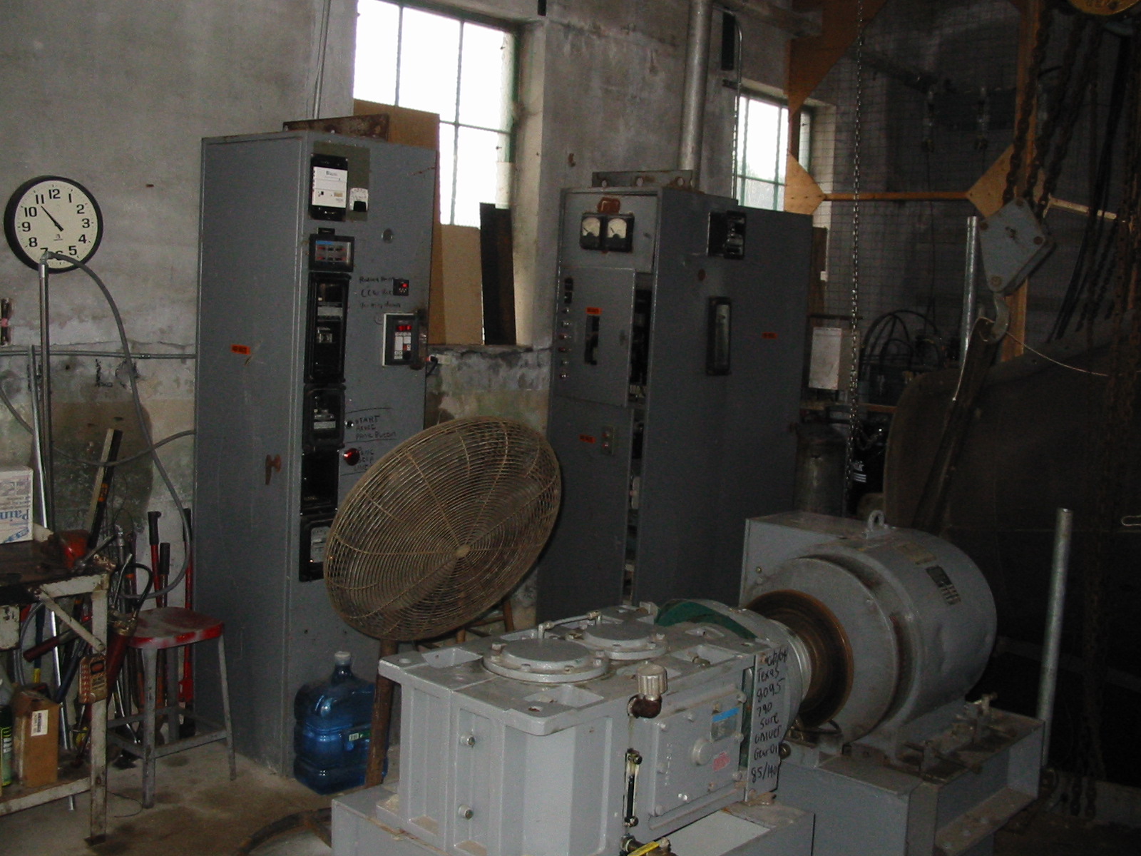
Overview of Unit One. Note protective relays, Minco temperature relay and tachometer relay in left cabinet. Large fan was used to cool the gearbox during the summer months.

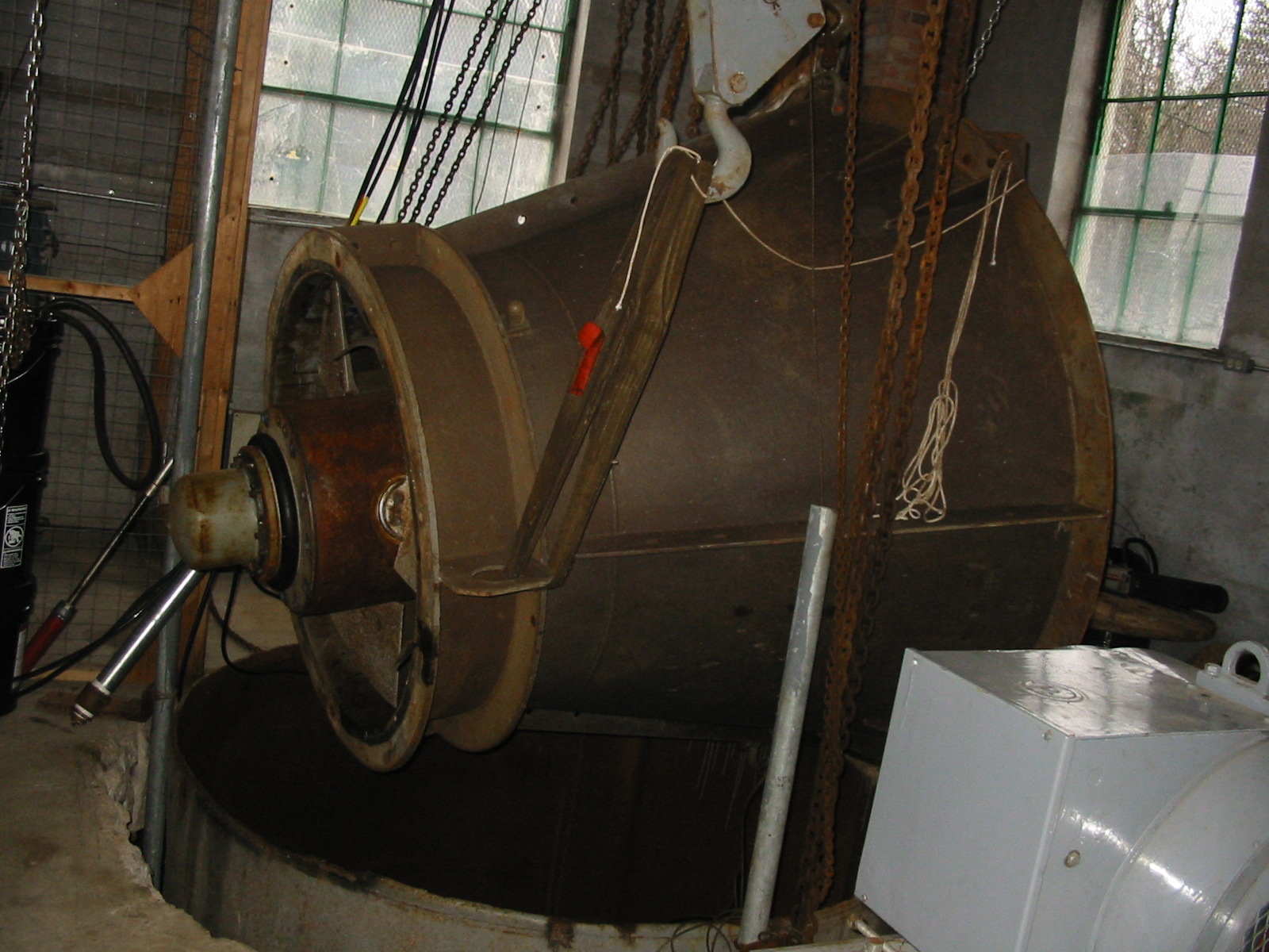
Unit Two ready to be lowered through its cylinder gate down onto its seat.