Pouring a Babbitt Bearing Web Page
March 28th, 2013
We had a babbitt radial bearing that needed to be repoured. In addition the intermediate shaft where the bearing journal is located needed to be refinished. We received a quote of $7000 to pour and machine the bearing. We decided to do it ourselves. Here is how we did it:
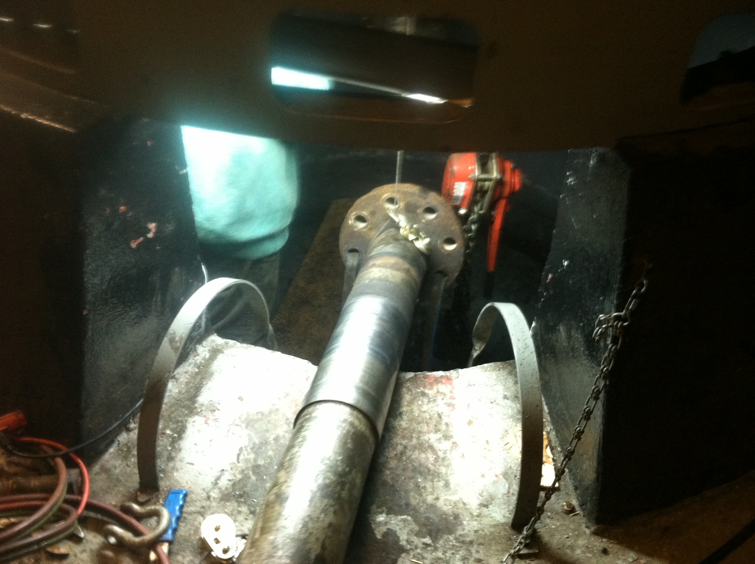
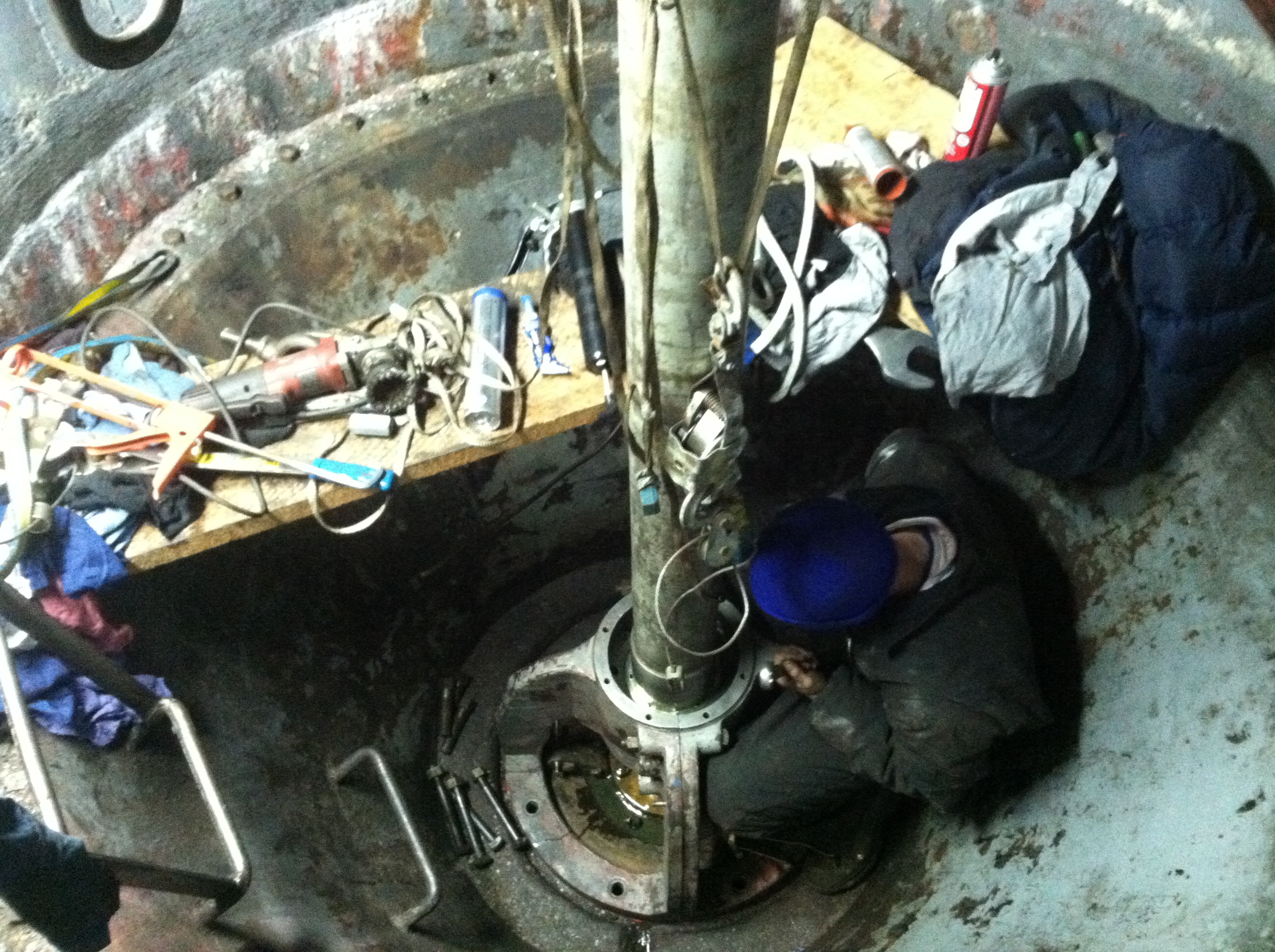
Will has detached the main shaft. We have rigged it out of the pit. The half coupling on the end of the shaft is attached to the top of the runner with 1 1/2 inch studs and nuts. The shiny surface is the scoured bearing journal.
You are looking down at the top of the Francis runner. My foot is resting on the flange where the stuffing box is bolted down. The runner has not dropped into the draft tube because Leffel turbines incorporate a step in the bed ring that prevents the runner from dropping.
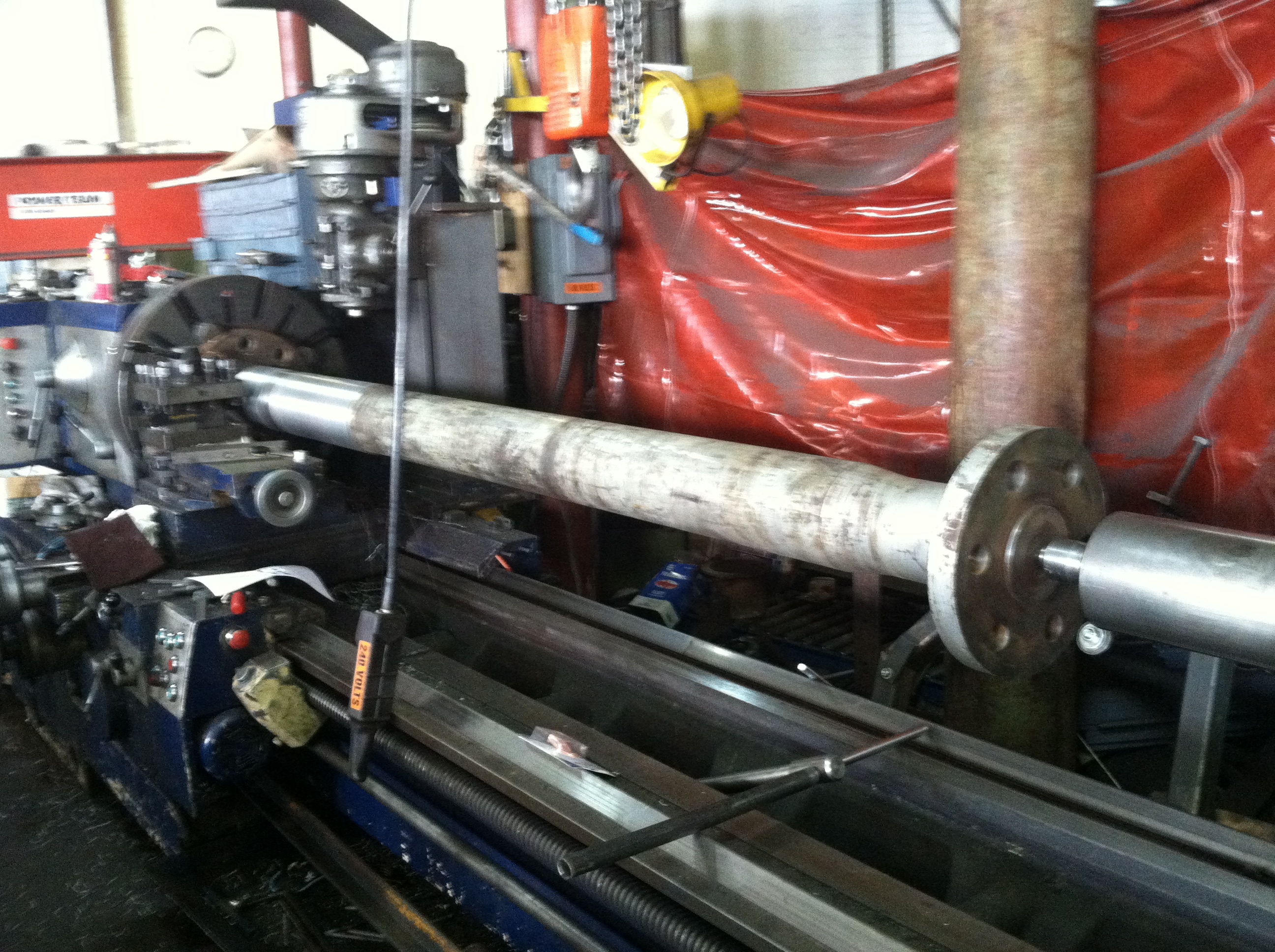
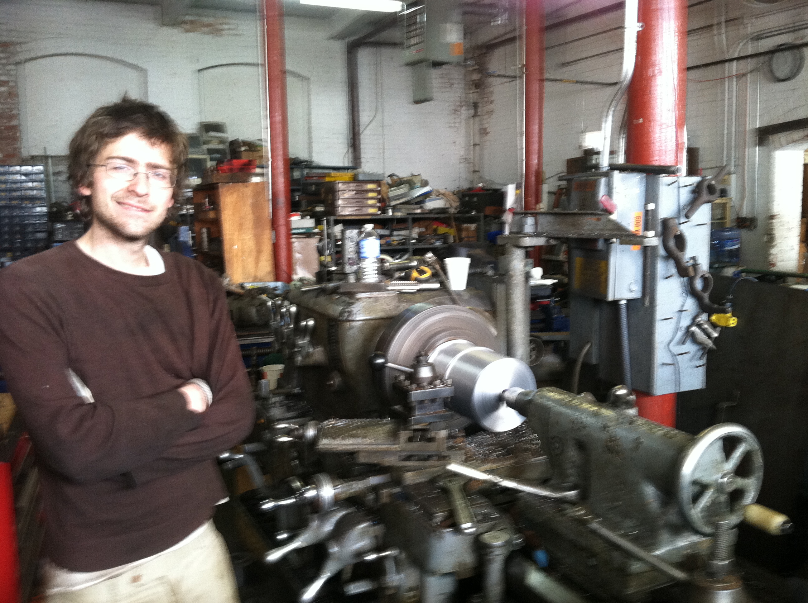
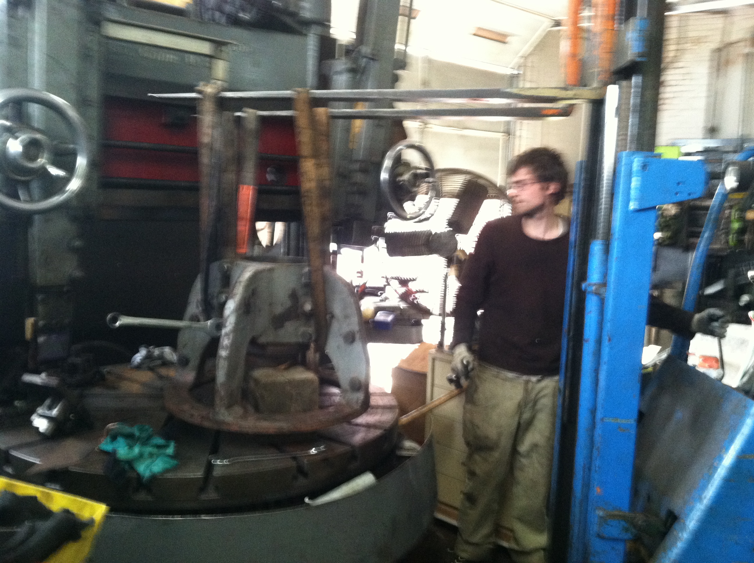
Will has installed the turbine main shaft into our Poreba roll lathe. The center hole on the generator end was not exposed to water and was still usable. He indicated the turbine end in the four jaw chuck.
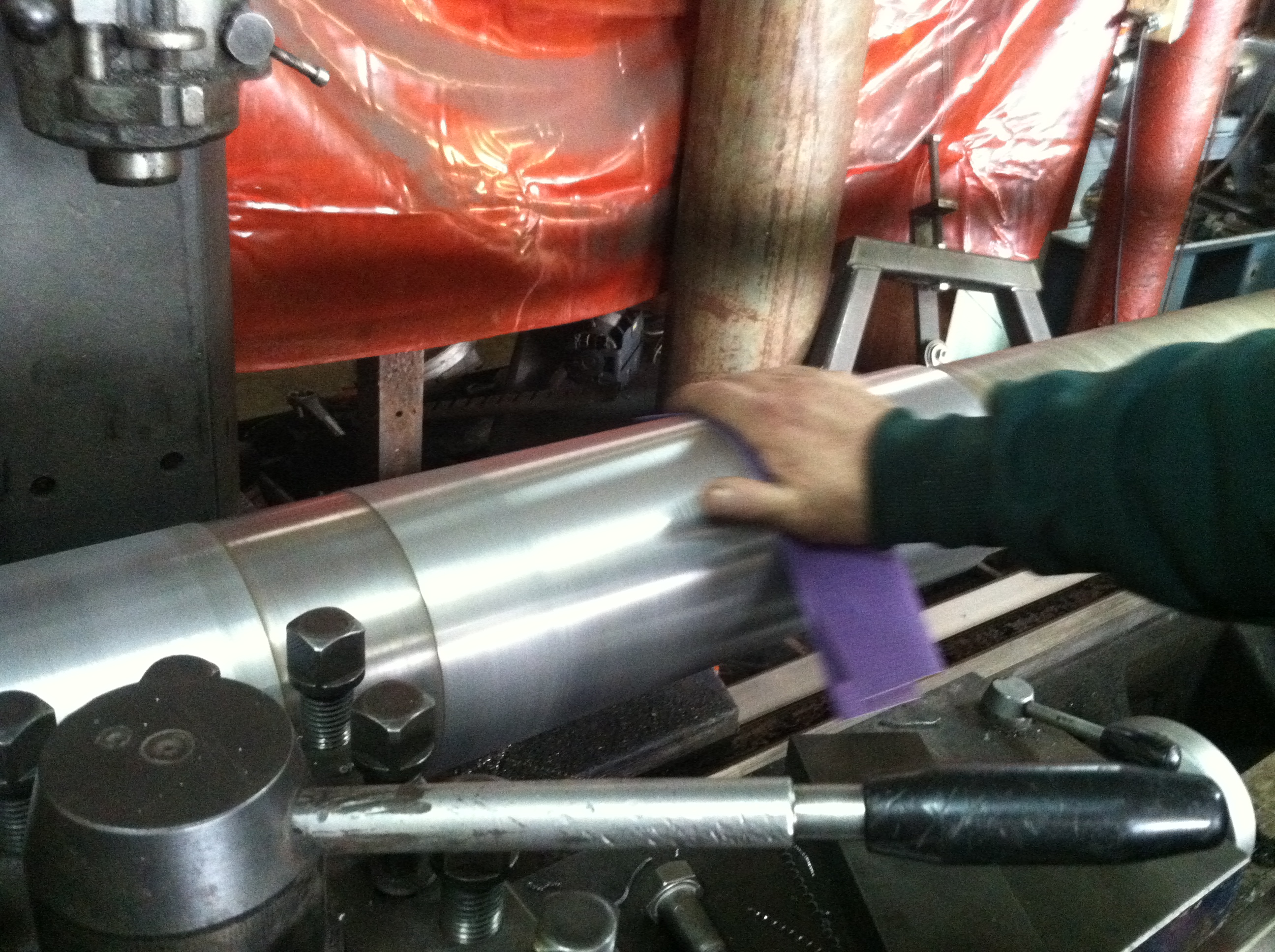
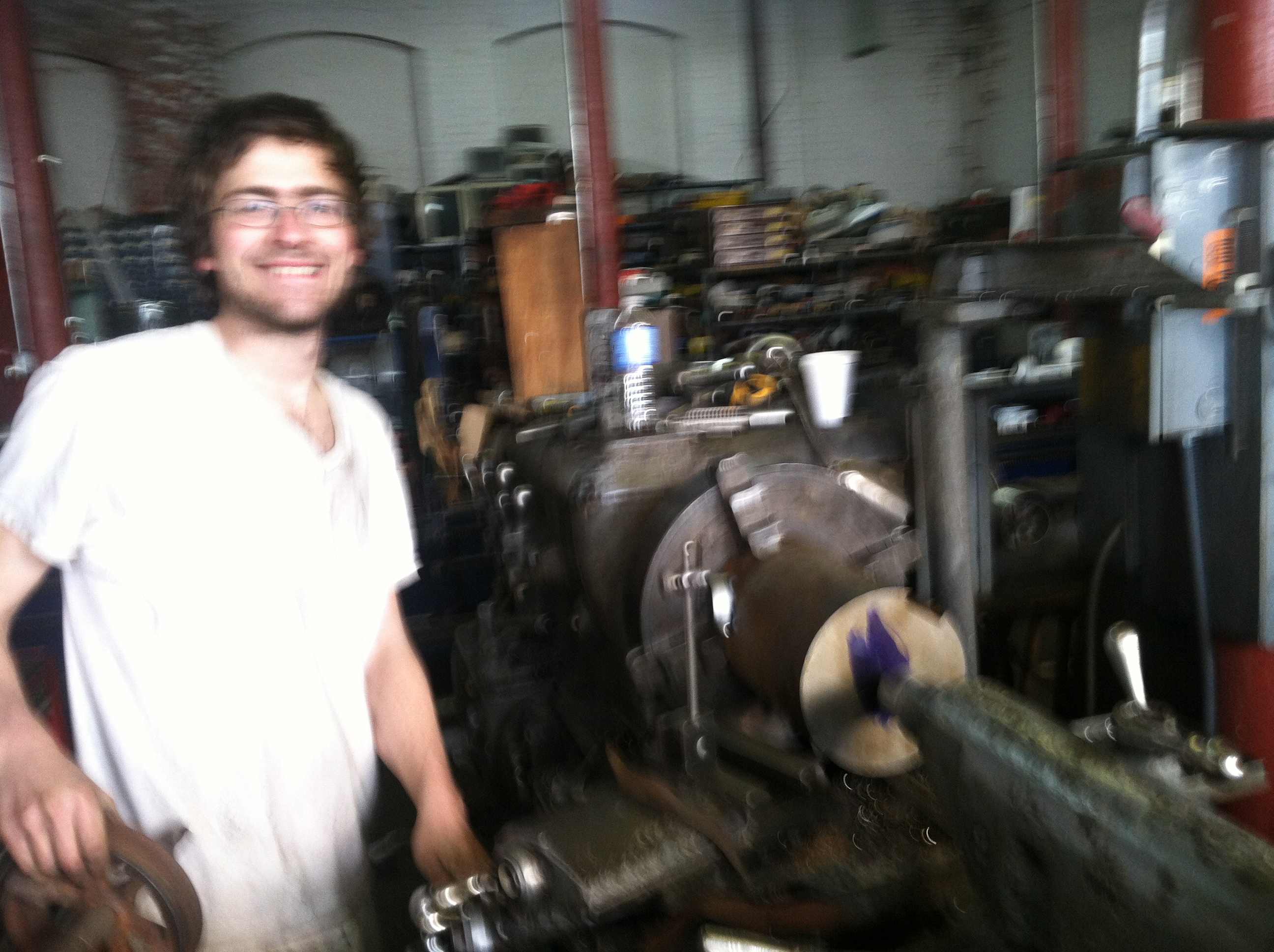
Here, Will is polishing the finished journal prior to removing the main shaft from the lathe.

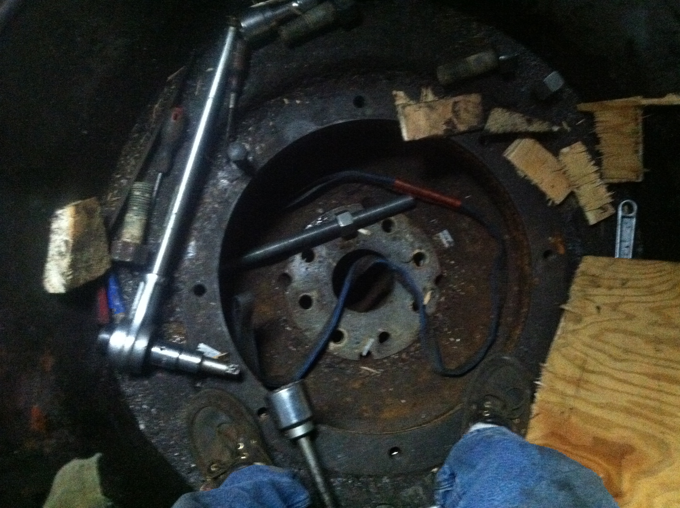
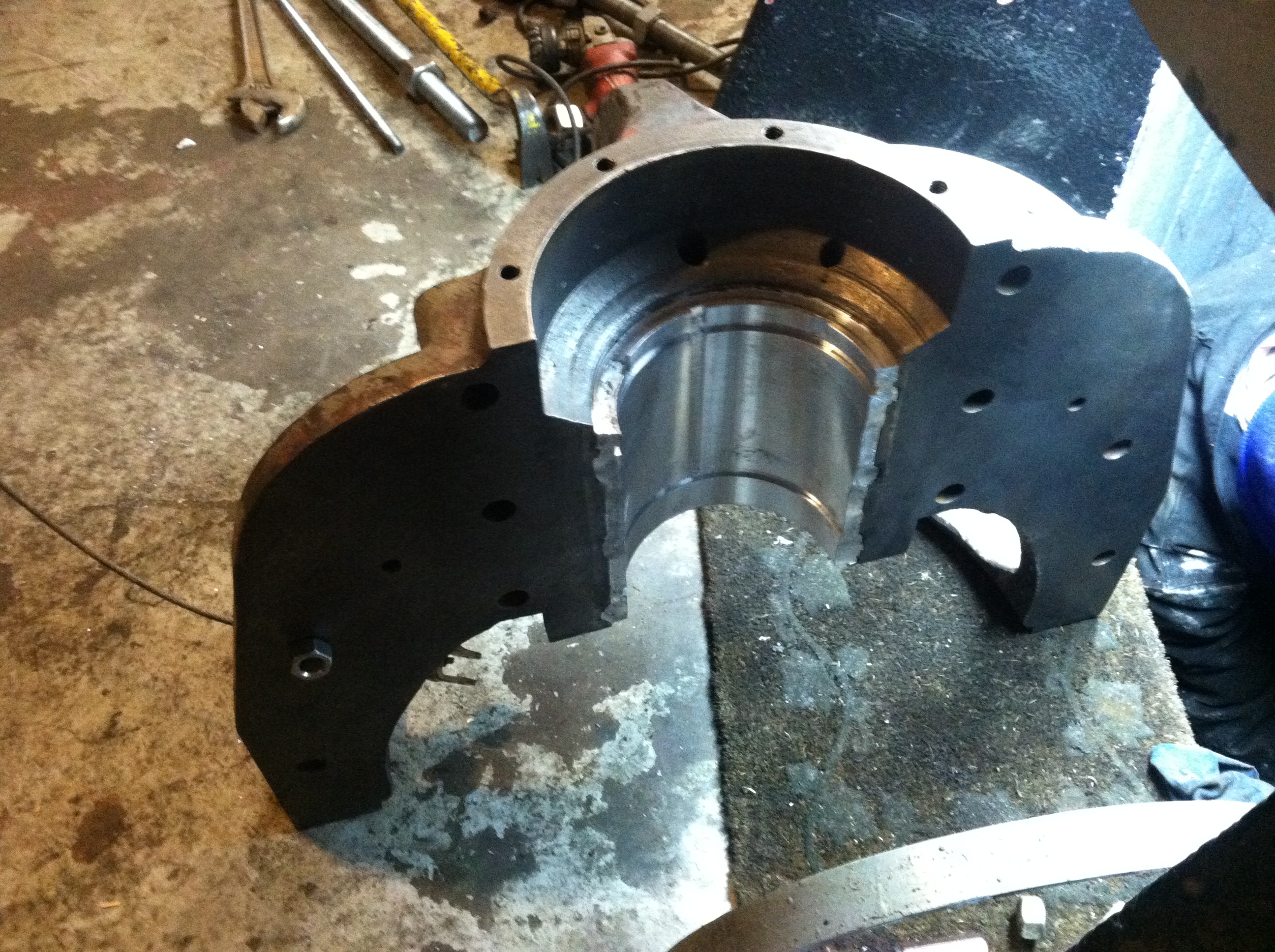
Here is the radial bearing prior to melting the old babbitt out of the cast iron housing.
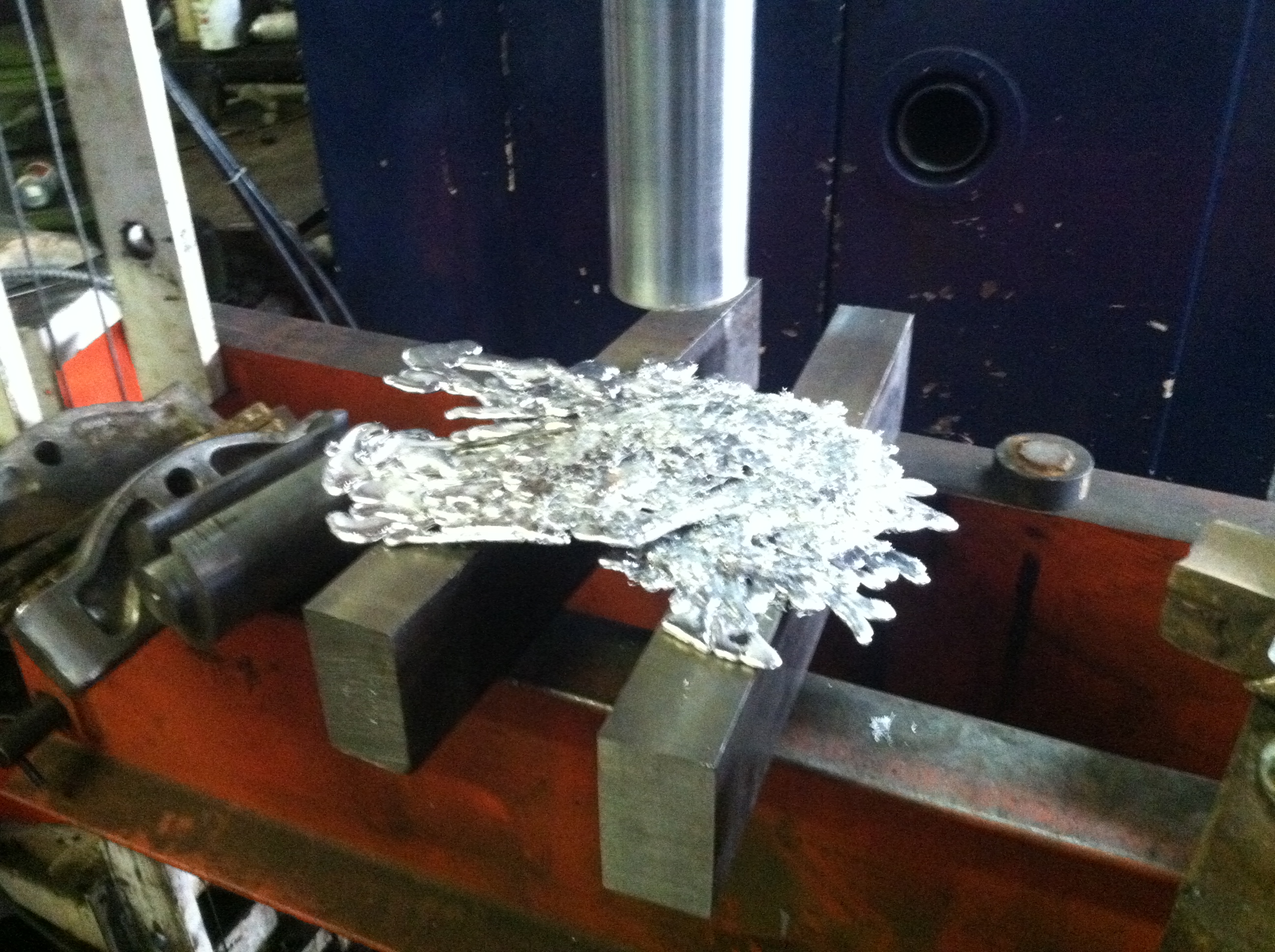
Here is some of the babbitt that I melted from the bearing. Previously we scrapped out a GE motor and I kept the bearing journals for their babbitt. Notice the snow white color of the Leffel babbitt. When I subsequently melted the babbitt from the GE bearings it was a beautiful golden color. We melted the two babbitt metals together in a ladle and thoroughly mixed the metals.
In order to pour the molten babbitt into the bearing, we took a chunk of old shafting and turned it down. For most of its length we turned it 1/4 inch less than the main shaft diameter. We stepped it up to the inside diameter of the the housing bore, for about 3/4 inch. We than stepped it up to the original diameter of the round stock.
Will is turning the faux turbine shaft that will be clamped in the cast iron bearing housing.
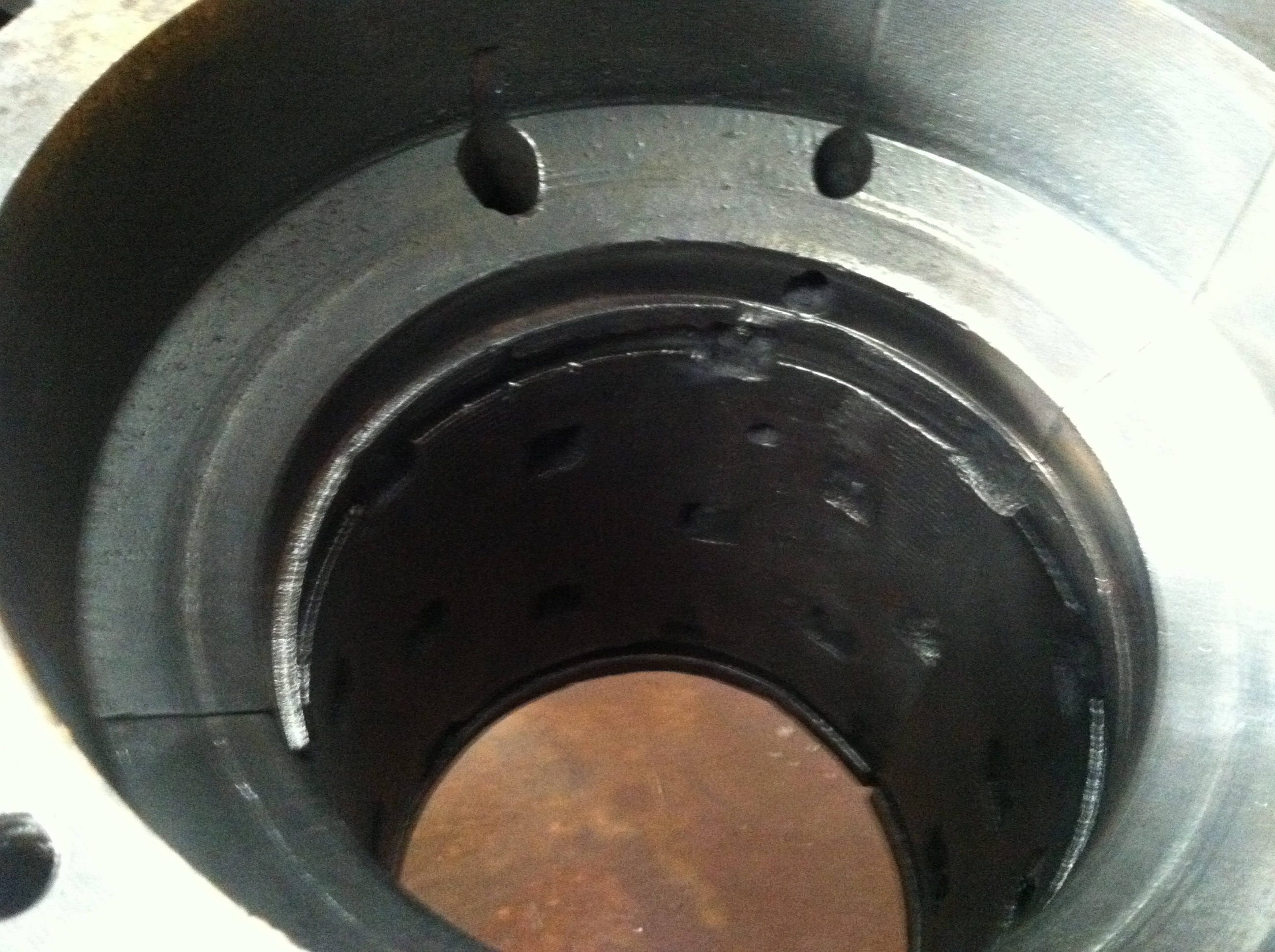
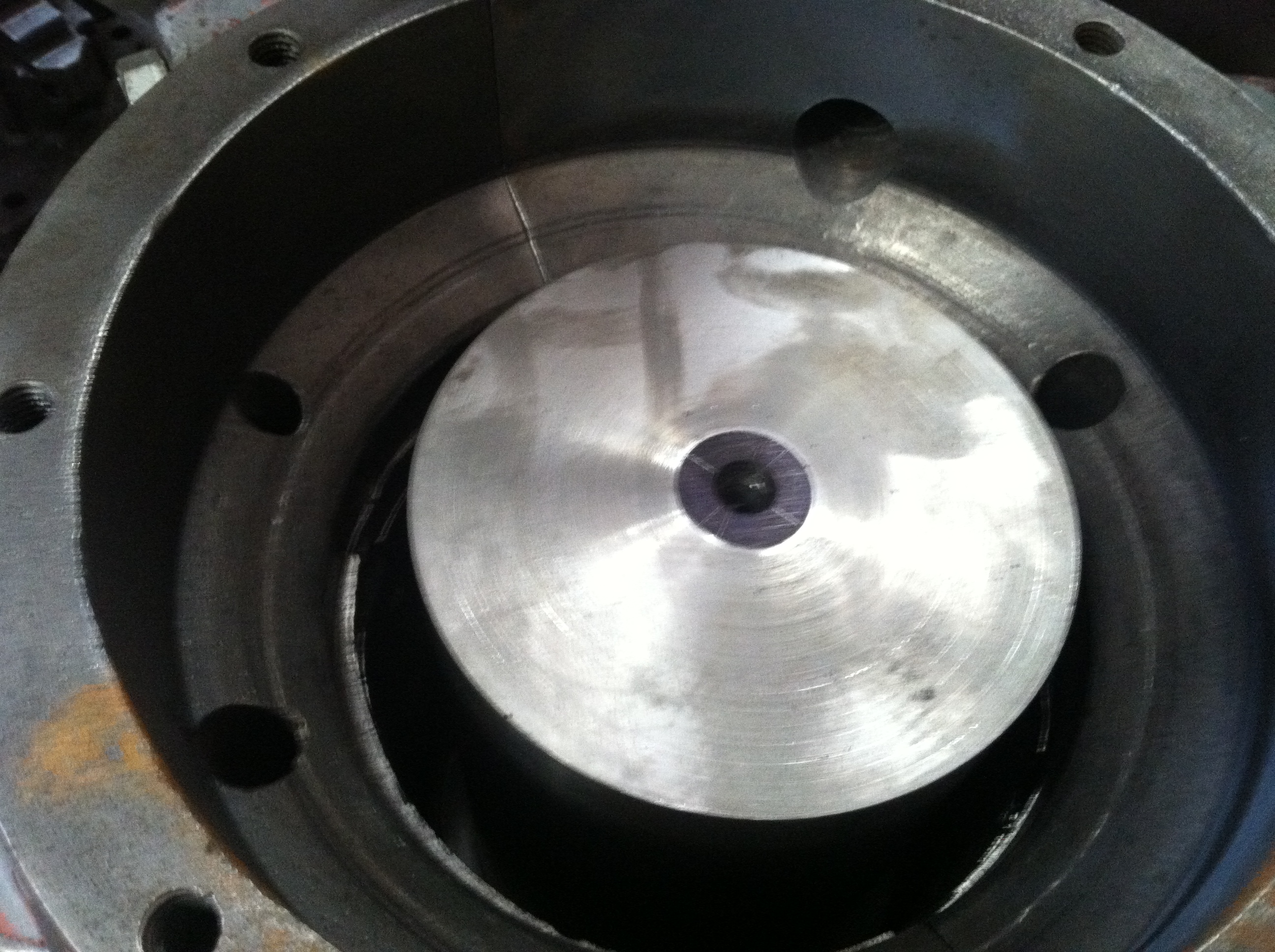
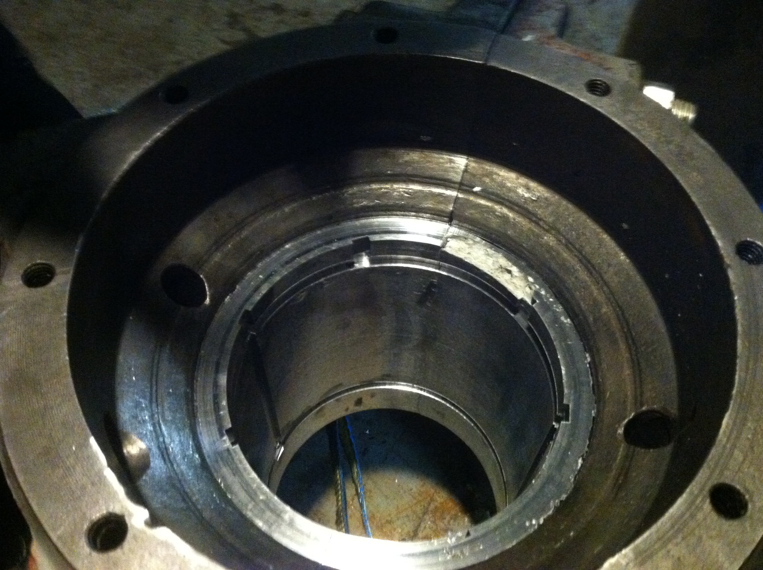
This is a view down the bearing bore of the cast iron housing after I had melted out the bearing. Note the square holes in the surface of the bore used to mechanically lock the babbitt in place. I wire wheel brushed the bore and decontaminated it with electric contact cleaned prior to pouring the molten metal.
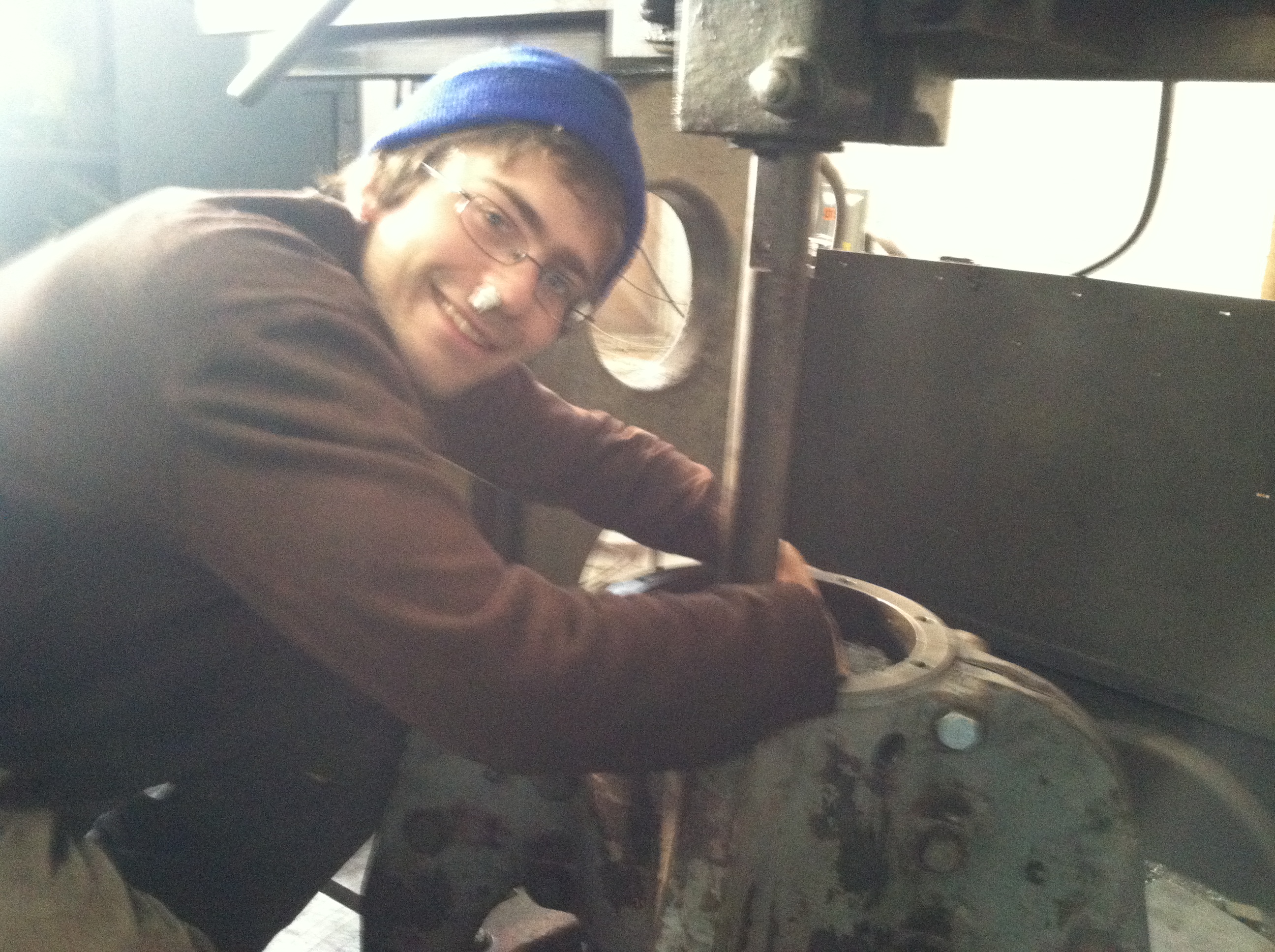
Will is using the forklift truck to lower the assembled and sanitized bearing housing onto the faux shaft. Just prior to this he lit the oxyacetylene torch with just the acetylene jet. He used the heavy carbon smoke to coat the faux shaft to prevent the babbitt from sticking to the shaft.
Here is the faux shaft bolted in place for sizing. We added aluminium flashing separators. The separators were clamped between the bearing halves and extended to the faux shaft. These were added so that after the molten babbitt cooled, we could separate the two halves of the split bearing.
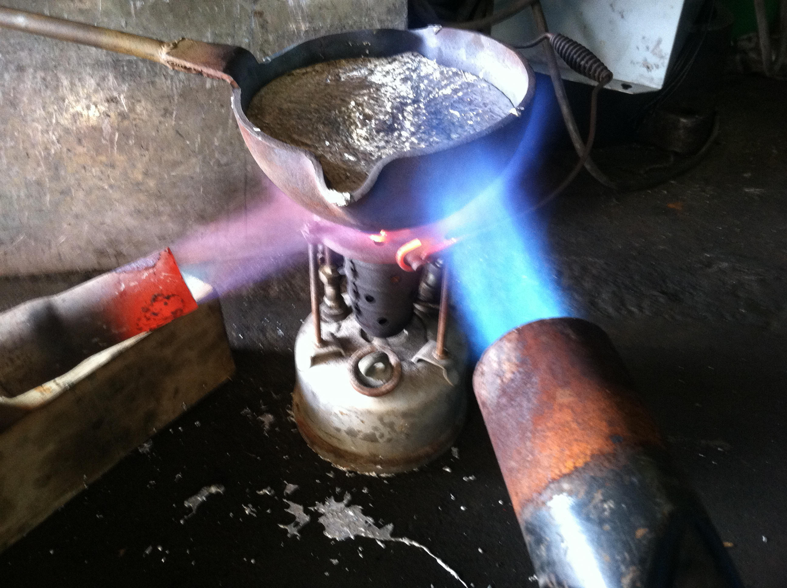
We used a babbitt pot and two propane berthas connected to barbecue grill tanks to melt the babbitt. We are using a foundry ladle to hold the molten metal.
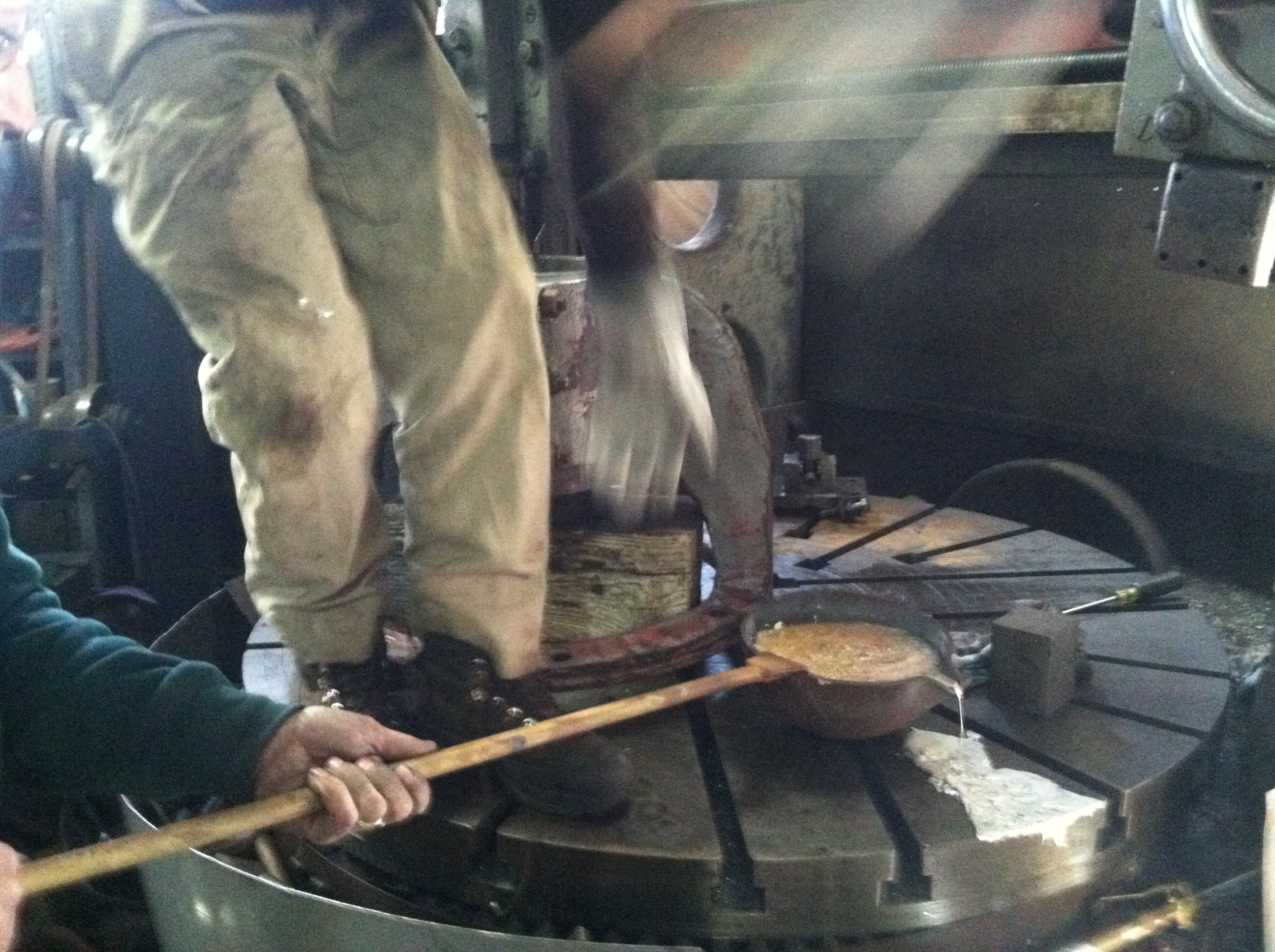
We are passing the ladle to Will.
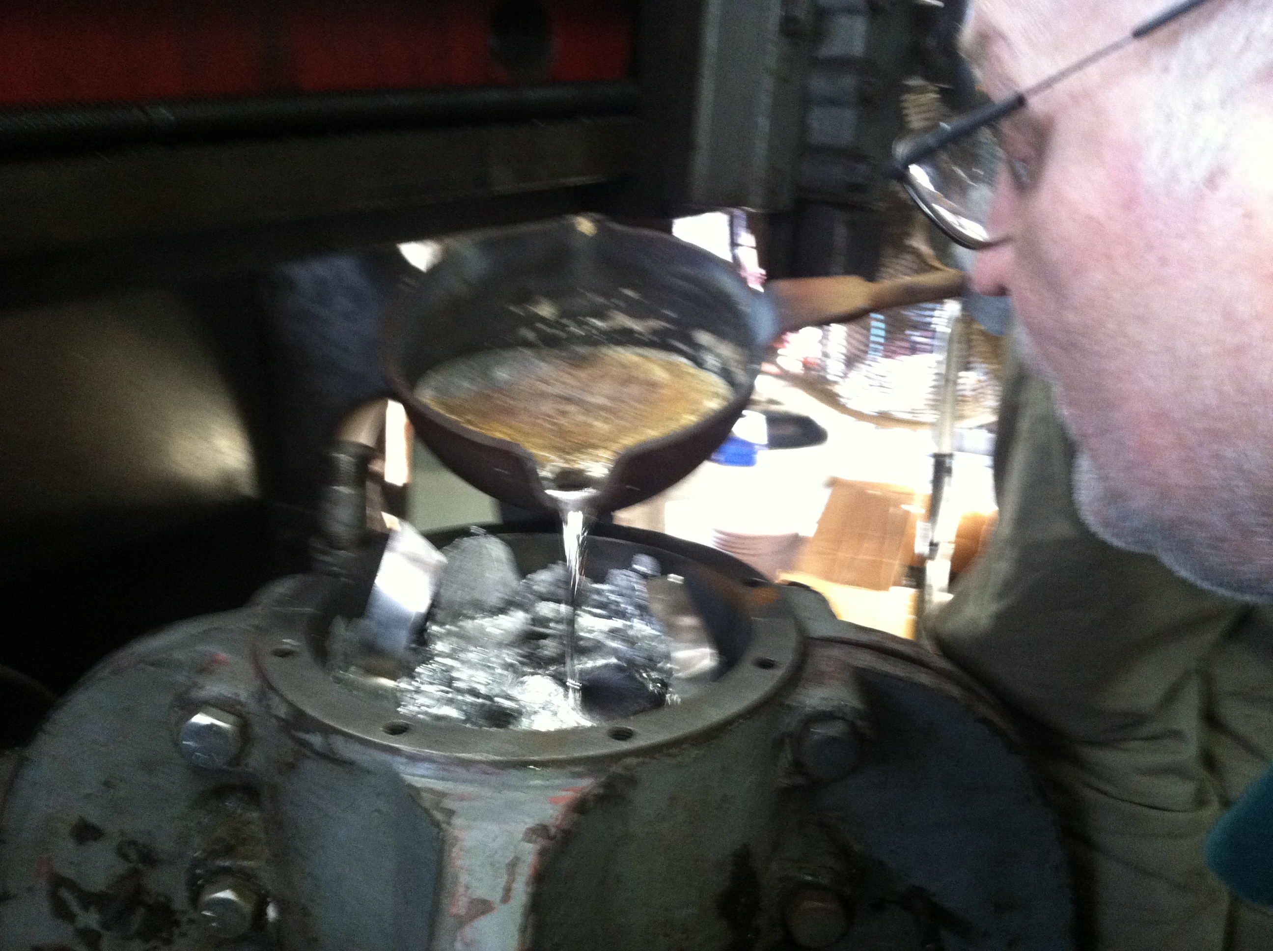
Warren is supervising the pouring of the molten babbitt into the bearing housing. Note the aluminium flashing used to separate the two sides of the bearing.
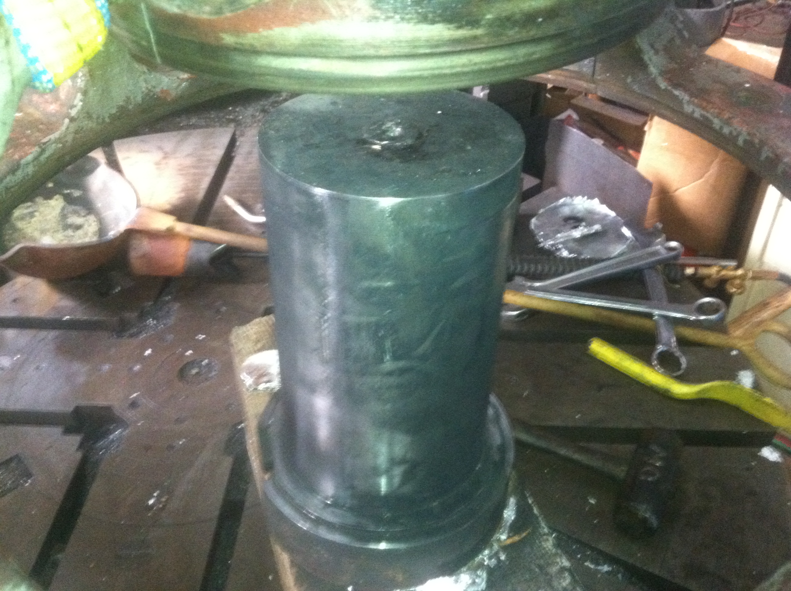
This is the next morning. The carbonized faux shaft has been extracted from the newly babbitted bore.
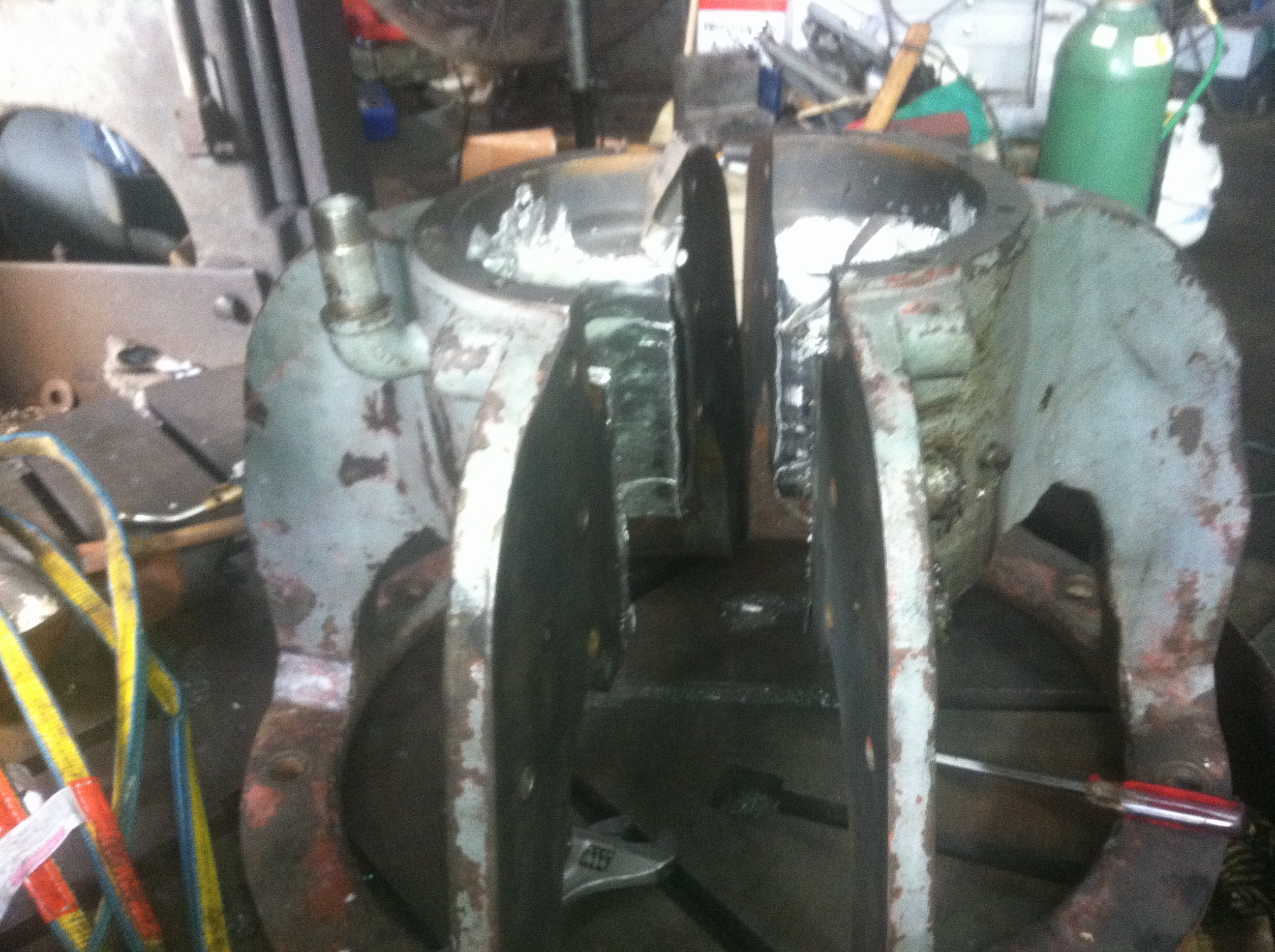
Will has successfully split the housing in half.
Will is checking the bore diameter after taking a pass with the Bullard vertical turret lathe.
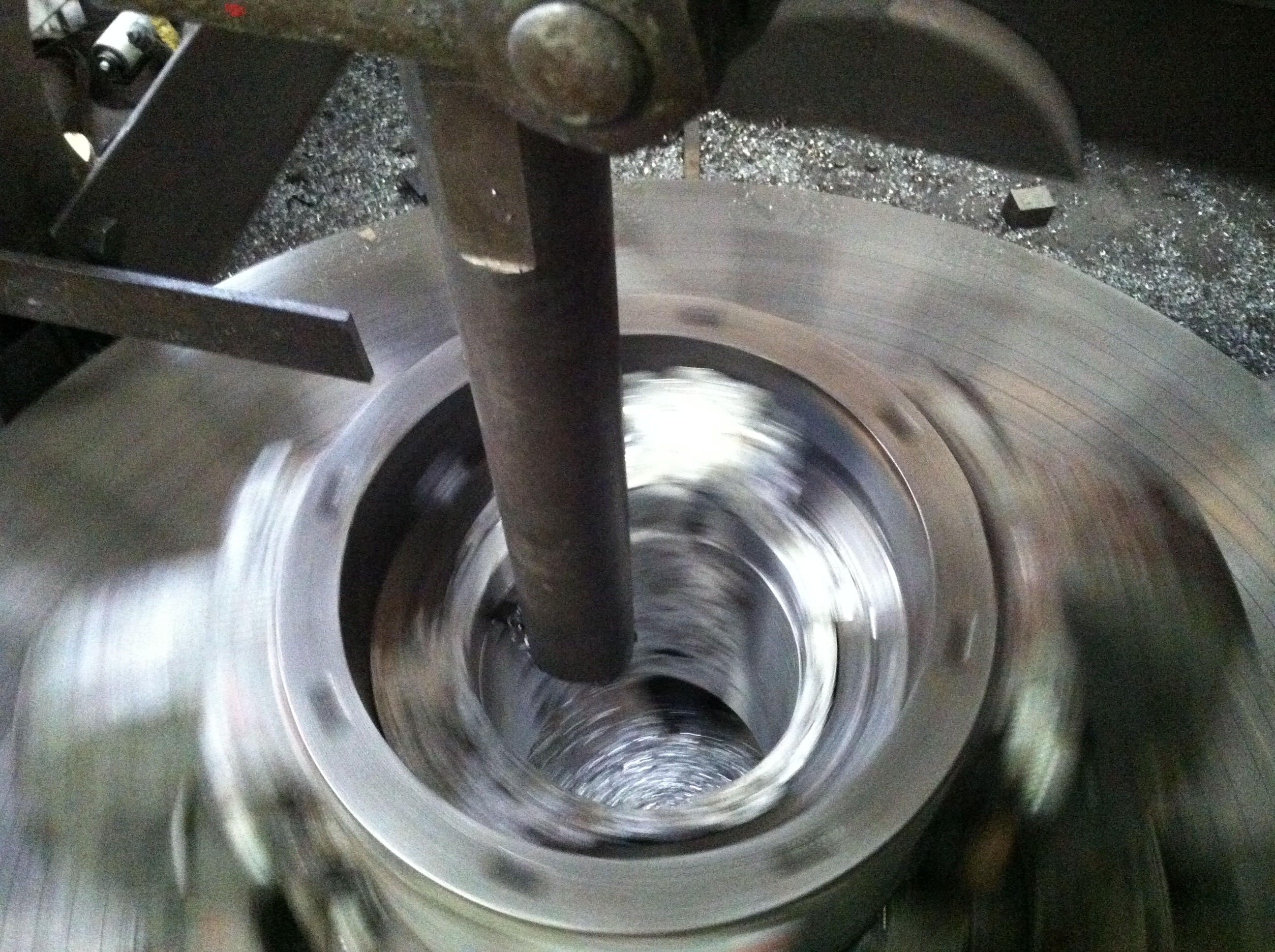
Looking down the babbitted bearing bore while it is being turned with a carbide single point tool.
Here is the finished bearing. Note the horizontal and vertical grooves machined into the surface of the babbitt. They are used to distribute the oil around the turning shaft. Note the two vertical holes drilled into the bearing housing on ether side. This bearing has an unusual pumping system. The bearing housing is stationary. Beneath the bearing housing is a cast iron bowl that mounts to the shaft and rotates with it. The bowl is filled with oil. A precisely bent brass tube is attached to the bottom of one hole. Its other end points into the oil. As the shaft rotates the oil and bowl, the oil is forced into the tube and is pushed to the top of the bearing. The oil spreads out and drops into the clearance between the shaft and the beating. The excess oil drops back into the bowl through the diametrically opposite hole.
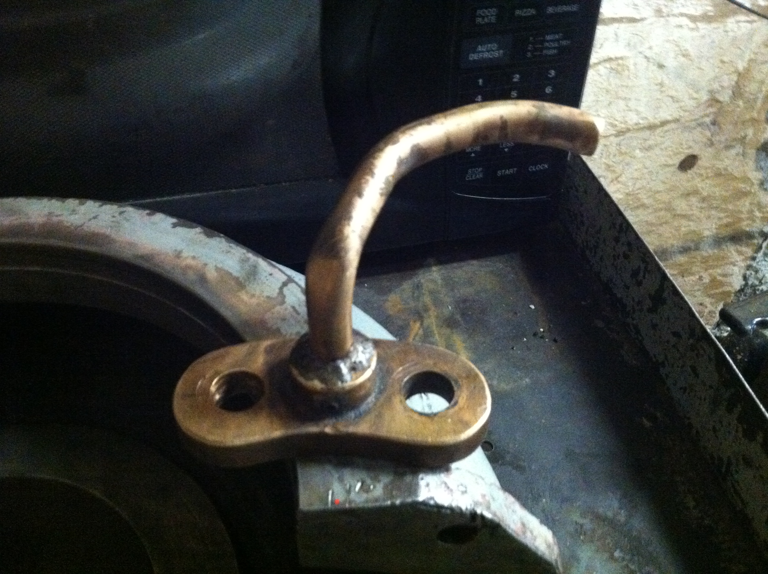
This is the bent piece of brass pipe that forms the entrance to the pump. It is resting on one half on the split bowl.
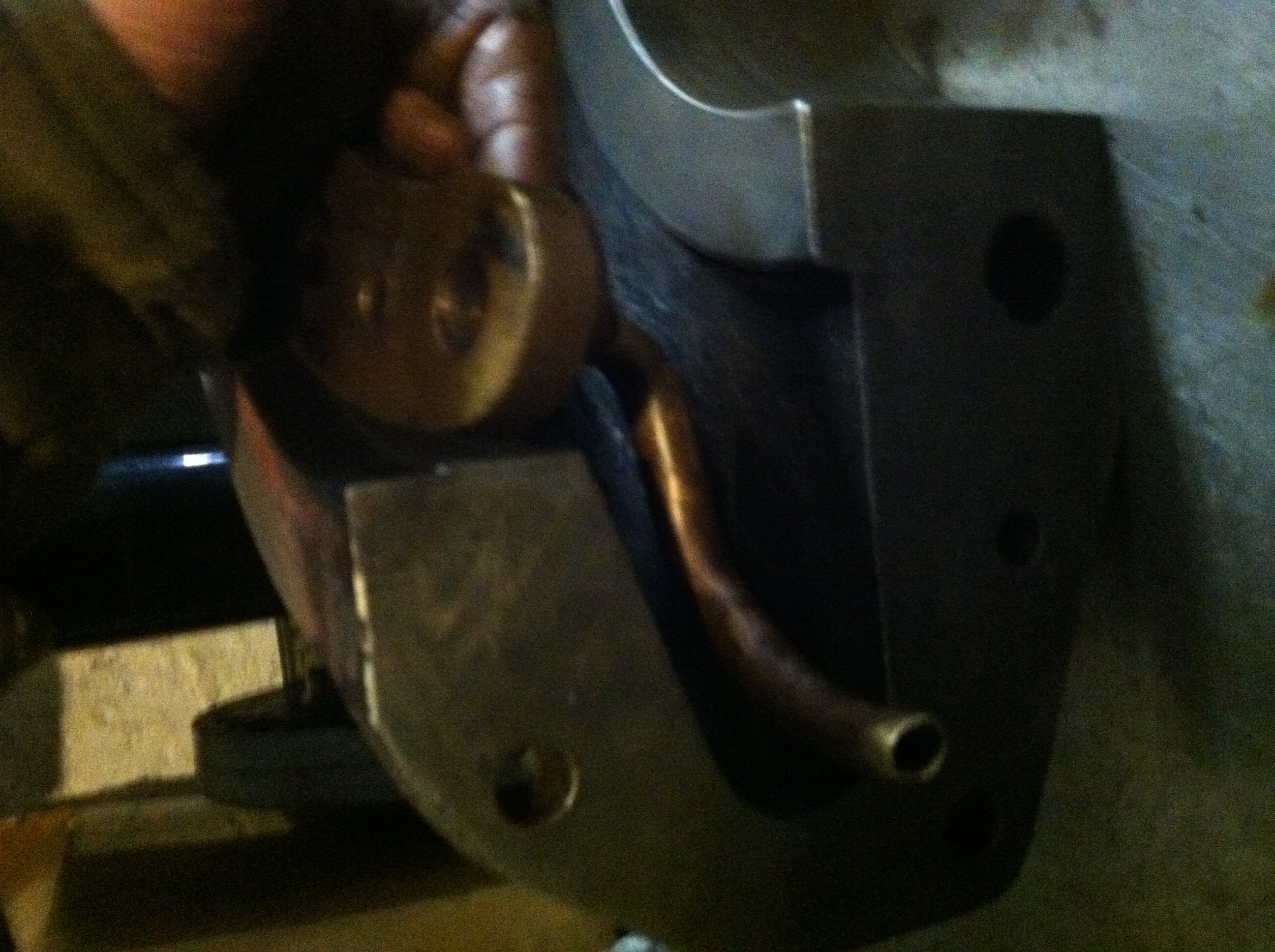
I am demonstrating how the pump pipe is installed and how it works.
Another view of the finished bearing prior to rigging it into the hole.
Will has re-installed the main shaft. It has been bolted to both the generator shaft and to the top of the runner. He has rigged the two halves of the bearing housing into the pit. He coated the bearing journal with blueing compound and turned the generator shaft. He re-split the bearing and scraped the high spot off of the babbitt bearing surface with a bearing scraper. He has now re-assembled the bearing. Note the bronze stuffing gland beneath the bearing. The rotating oil bowl has not been installed at this time.