 GREEN
GREEN
AND
CLEAN
POWER
French River Land Company's Website!
|
AND CLEAN POWER French River Land Company's Website!
|
|
French
River Land Company's Home Page!
Rebuilding 120" Niles Boring Mill HYDROELECTRIC SITES: Anasagunticook Lake Dam Replacement- C.Fay & W.Fay Appleton Wisconsin Anniversary Senor Bonifettis' sites in Chile Turners Falls Generator Rewind USEFUL ENGINEERING: Admitting Air to Turbine Runners Improves Efficiency, S. Logan Kerr Air Admission to Hydro Runners, David Cox, USCOE, Kerr Dam A Self-Adjusting Spring Bed Bearing- Henry G. Reist ASME 1646 The Banki Water Turbine Mockmoore and Merryfield Bearing Currents: Their Origin and Prevention C. T. Pearce Bishops Method- STABGM Program Blade Pitting- Boving LTD 1930 Cavitation- Accelerated Research, Allis Chalmers Research Cavitation & Vibration of a Draft Tube Cavitation- Prevention & Reduction, Allis Chalmers Research Causes & Effects of Cavitation in Hydraulic Turbines Chain Turbine by: Nguyen Minh Duy Chain Turbine Mechanics- Discussions with Duy Characteristics of Modern Hydraulic Turbines-Chester Larner Comparative Tests On Experimental Draft Tubes- C M Allen & I A Winter 1923 Design of an Overshot Waterwheel (by Carl Weidner) Design of Small Water Turbines for Farm and Small Communities Design of the runner of a Kaplan turbine for small hydroelectric power plants: Timo Flaspöhler Draft Tubes of Hydro-Electric Stations by M. F. Gubin Ejection into Tailraces of Hydropower Plants: S. M. Slisskii Erection & Alignment of Vertical Waterwheel Generator Units-R.O. Standing Evolution of Hydraulic Prime Movers-Byron McCoy Fall Increaser Herschel Venturi Tube Fall Increaser Moody Ejector Turbine Fall Increaser Hydraulic Jump Apron Generator Shaft Design Calculation- Olav Hodtvedt Governor Theory for the Plant Operator Graphics of Water Wheels- William Fox Hydraulic Motors- M. Bresse & F. A. Mahan 1869 Hydraulic Power Transmission by Compressed Air Hydraulic Rams their Principals and Construction by J. Wright Clarke Hydraulic Turbine and Governor Field Erection Information Hydraulic Turbines- Robert Long Daugherty Hydraulic Turbines by Arnold Pfau Hydraulic Turbines Gelpke & Van Cleve Hydrokinetic Energy in Massachusetts, William D. B. Fay HYDROTURBINES DESIGN AND CONSTRUCTION N. N. KOVALEV Impulse Turbines by Ely Hutchinson Interference fitting a large runner shaft Kaplan Blade Design NACA Air Foil- Report No. 460 Kaplan Blade Design NACA Air Foil- Report No. 628 Kaplan Design Marko Kogovsek.xls A Laboratory Study to Improve the Efficiency of Crossflow Turbines- N. Aziz & V. Desai Loading Vertical Thrust Bearings R. C. Johnson Low Head Hydroplants, Emil Mosonyi Meggering Earth Resistance Motors as Generators for Microhydro, Nigel Smith Operation & Maintenance of Hydro-Generators Out Gassing of Cross Flow Turbines Parallel Operation of Turbines Analysis Powerhouse Design- Miniwatt Hydro Rack Design-Chicopee-Olav Hotvedt Rack Design- Hydraulic Institue of Munich Rack Design-Flow Induced Vibrations Selecting Hydraulic Reaction Turbines BUREC Snows Improved Water Wheel Governor Standard for Hydraulic Turbine and Generator Shaft Couplings and Shaft Runout Tolerances Stoplog Structure Design Calculation Stress Analysis of Hydraulic Turbine Parts, BUREC- F.O. Ruud Some Fluid Flow Characteristics of a Cross Flow Type Hydraulic Turbine- Durgin & Fay Technology of Heavy Electric Machine Building HydroGenerators Tenth Census of the US, 1880, Water Power of the US, Part I- Professor Trowbridge Tenth Census of the US, 1880, Water Power of the US, Part II- Professor Trowbridge Tests on a Kaplan Hydraulic Turbine Theoretical Conditions Related to an Open Channel Flow Linear Turbine- Ishida & Service Theory of Turbines- De Volson Wood Tidal Energy for Hydroelectric Power Plants by L. B. Bernshtein Treatise relative to the Testing of Water-Wheels and Machinery, James Emerson 1879 Trash Rack Differential Equations 2L/3 Trashrack Differential Equations General Solution f(x) Turbine Water-Wheel Tests- Robert Horton Turgo, A High Speed Impulse Turbine- Paul Wilson Water Hammer and Surge Tanks G. V. Aronovich Water Hammer-Lorenzo Allievi-Text Water Hammer-Lorenzo Allievi-Figures Water Hammer-ASME Symposium 1933 Waterpower Engineering-Daniel Webster Mead Water Turbines Contributions to Their Study, Computation and Design-S.J. Zowski TRADE CATALOUGES: ASEA- Bearings for Large Vertical Hydro-Electric Machines Bradway Turbine (progressive gate) Christiana Machine (register gate) Electric Machinery Company (EM) General Electric- Standard Specifications for Hydro Thrust Bearings and Runners Head Gate Hoists- S. Morgan Smith J & W Jolly (cylinder gate) Lombard Direct-Connected Oil Pressure Governors Bulletin N0. 113 October 1st, 1912 Lombard Governor Company Type T Instruction Book Lombard Governors for Waterwheels and Steam Engines-1902 Lombard Water Wheel Governors Catalouge 26 Ridgway Perfection Water-Wheel Vertical Shaft Water Wheel Driven Generators- General Electric Westinghouse Small Vertical Waterwheel-Driven A-C Generators, July 1944
Links:
Small Turbine Manufacturers Websites: www.waterturbine.com
|
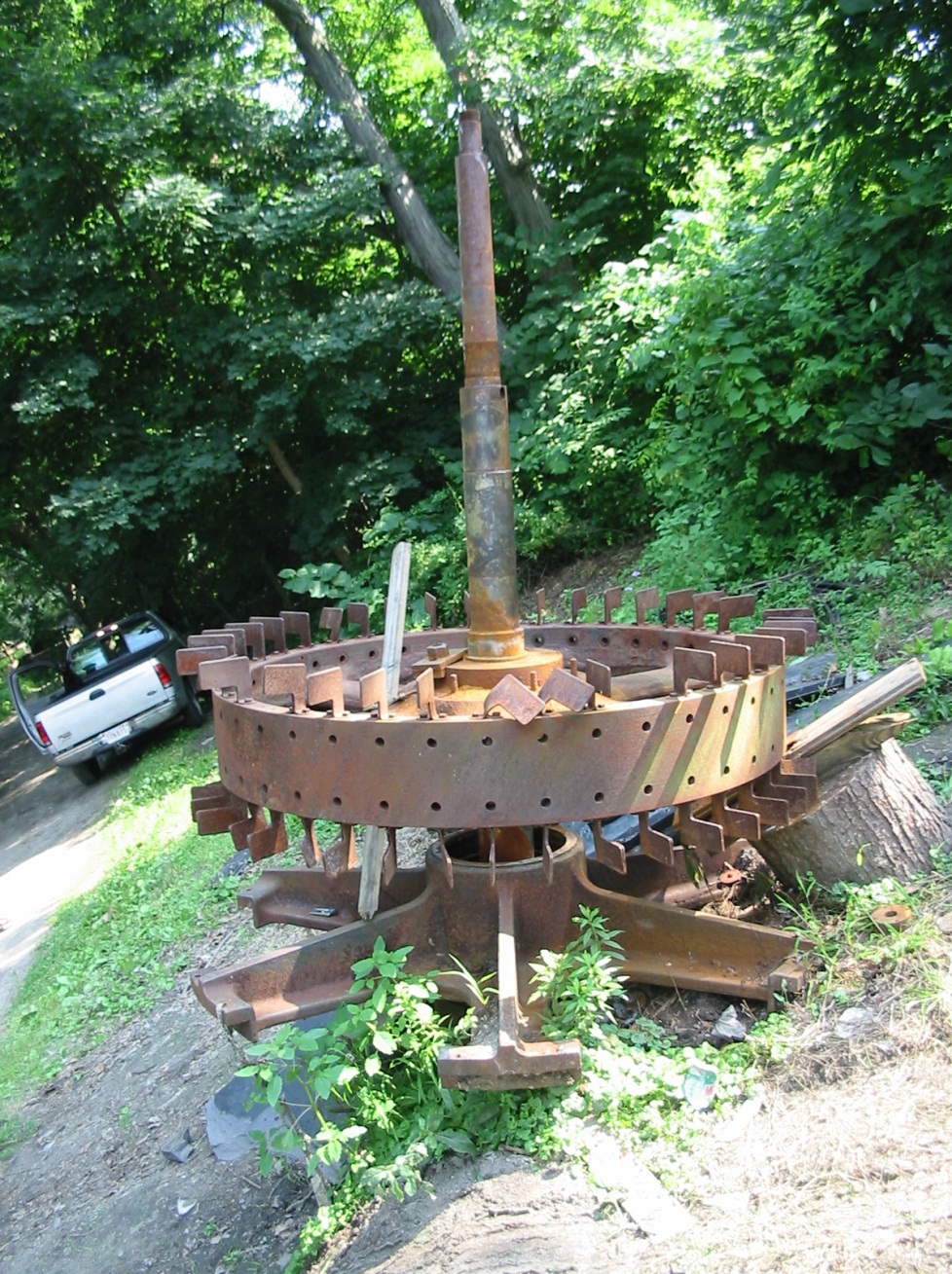
Pole Key Extraction Webpage Pole and Pole Key Extraction and Installation Methods Pertaining to ASEA and Electrosila Generators I) Introduction: One of the more formidable and dreaded tasks, when rebuilding a salient pole, synchronous alternator, is removing the pole pieces from the rotor rim. There are three common designs for securing the poles to the rim. The designs are: A) Design One: On the older and smaller, Westinghouse, General Electric and EM (Electric Machine) alternators the poles were bolted to the stator rim. The rim had either two or four sets of holes drilled through it at the location of each pole. Corresponding threaded holes were provided in the back surface of the pole. Hexagonal headed machine screws were used to bolt the poles to the rim. This design had drawbacks when applied to larger size alternators. They include creating localized stress concentrations in the rotor rim and the increasing number of bolts required to secure the pole to the rim. See Figure 1.
Figure 1: Carcass of Westinghouse rotor showing drilled holes in the solid cast iron rim that are the points for the salient poles. B) Design Two: A series of equi-distance, circumferential, dovetail slots are machined vertically into the outer radial surface of the rim. The corresponding inner, radial surface of the pole is constructed with a large dovetail. The pole is suspended over the rim of the generator with its dovetailed backside lined up with one of the dovetail slots. Depending upon the size and weight of the pole the suspension is done by hand, cum-a-long or bridge crane. The pole is slowly lowered into the dovetail slot until its vertical magnetic center matches the as assembled magnetic center of the stator. The pole is semi-permanently secured to the rim by the introduction of two full length parallel wedges. The wedges are machined in matching pairs. When the two sloping surfaces are placed together, facing each other, the outer surfaces are parallel to each other and they form an elongated rectangular bar. The combination of the two wedges is called a pole key. See Figures 2 and 3. One method uses a single pair of wedges that are the full width of the dove tail slot. The key is lowered into place between the pole and the slot. A support is placed beneath the lower end of wedge that is facing up. The wedge that is facing down is driven to refusal. As a result of the relatively long and shallow angle of the opposing wedges the resulting, normal force is very large. Through the static coefficient of friction the normal force produces a frictional locking force that prevents the pole from moving in the dovetail slot. Note that this method is forcing the pole away from the rotor rim. A second method uses either one or two sets of pole keys. Instead of inserting the pole key between the pole and its slot, the key or keys are inserted in the interface between the dovetail angle and the slot angle. . A support is placed beneath the lower end of wedge that is facing up. The wedge that is facing down is driven to refusal. As a result of the relatively long and shallow angle of the opposing wedges the resulting, normal force is very large. Through the static coefficient of friction the normal force produces a frictional locking force that prevents the pole from moving in the dovetail slot. Note that this method is forcing the pole against the rotor rim.
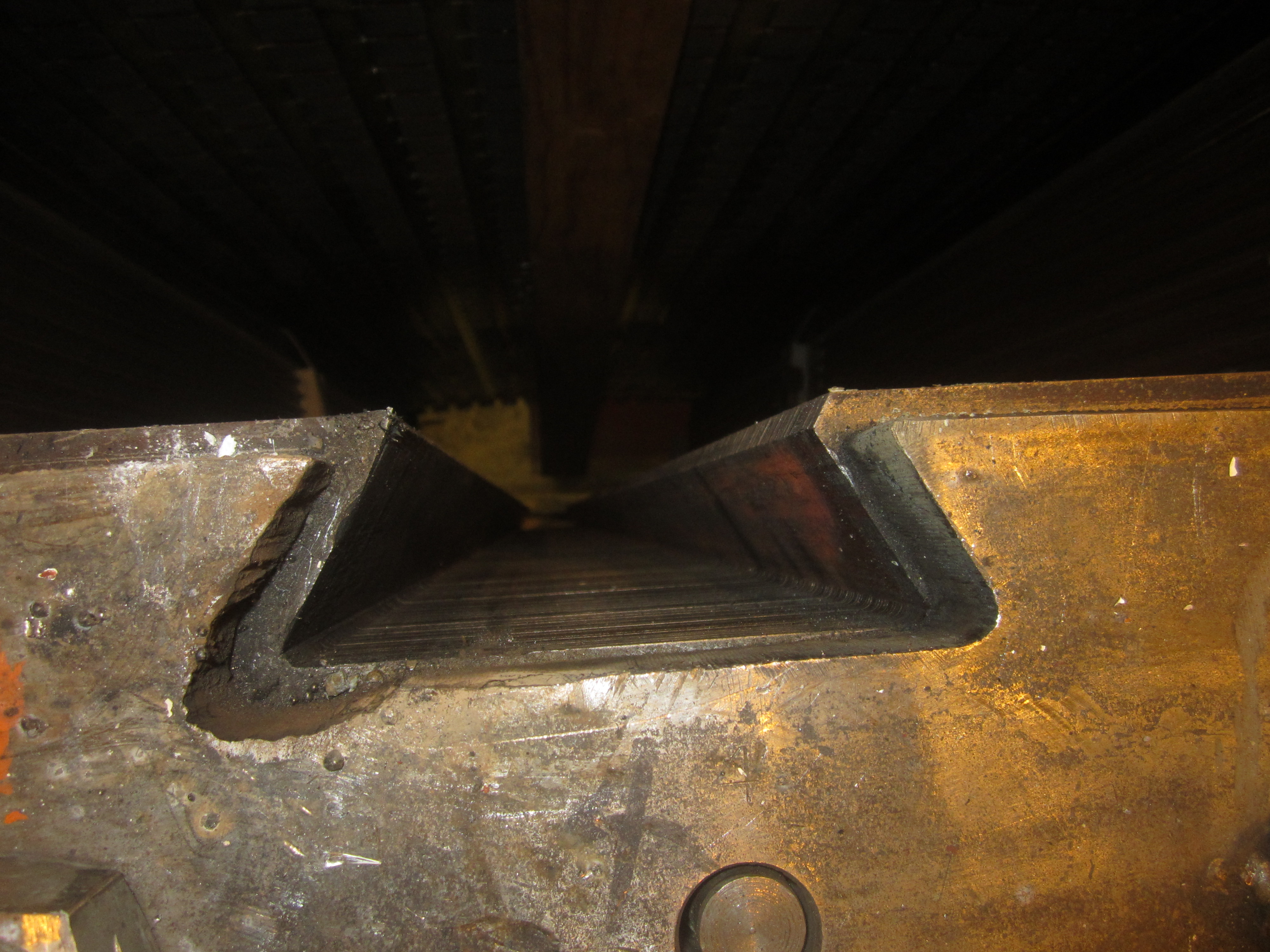
Figure 2: Dovetail slot in rotor rim.
Figure 3: Dove tail on back side of pole armature (note coil has been removed). C) Design Three: A series of equi-distance, circumferential, "Tee" slots are machined vertically into the outer radial surface of the rim. The corresponding inner, radial surface of the pole is constructed with a large "tee". The pole is suspended over the rim of the generator with its tee-ed backside lined up with one of the "Tee" slots. Depending upon the size and weight of the pole the suspension is done by hand, cum-a-long or bridge crane. The pole is slowly lowered into the Tee slot until its vertical magnetic center matches the as assembled magnetic center of the stator. The pole is semi-permanently secured to the rim by the introduction of two full length parallel wedges. The wedges are machined in matching pairs. When the two sloping surfaces are placed together, facing each other, the outer surfaces are parallel to each other and they form an elongated rectangular bar. The combination of the two wedges is called a pole key. See Figures 4 and 5. One method uses a single pair of wedges that are the full width of the Tee slot. The key is lowered into place between the pole and the slot. A support is placed beneath the lower end of wedge that is facing up. The wedge that is facing down is driven to refusal. As a result of the relatively long and shallow angle of the opposing wedges the resulting, normal force is very large. Through the static coefficient of friction the normal force produces a frictional locking force that prevents the pole from moving in the dovetail slot. Note that this method is forcing the pole away from the rotor rim. A second method uses either one or two sets of pole keys. Instead of inserting the pole key between the back of the pole and the back of the Tee slot, the key or keys are inserted in the interface between the small, radial inwards, facing surface of the slot and its corresponding small, radial, outwards facing surface of the Tee. A support is placed beneath the lower end of wedge that is facing up. The wedge that is facing down is driven to refusal. As a result of the relatively long and shallow angle of the opposing wedges the resulting, normal force is very large. Through the static coefficient of friction the normal force produces a frictional locking force that prevents the pole from moving in the dovetail slot. Note that this method is forcing the pole against the rotor rim.
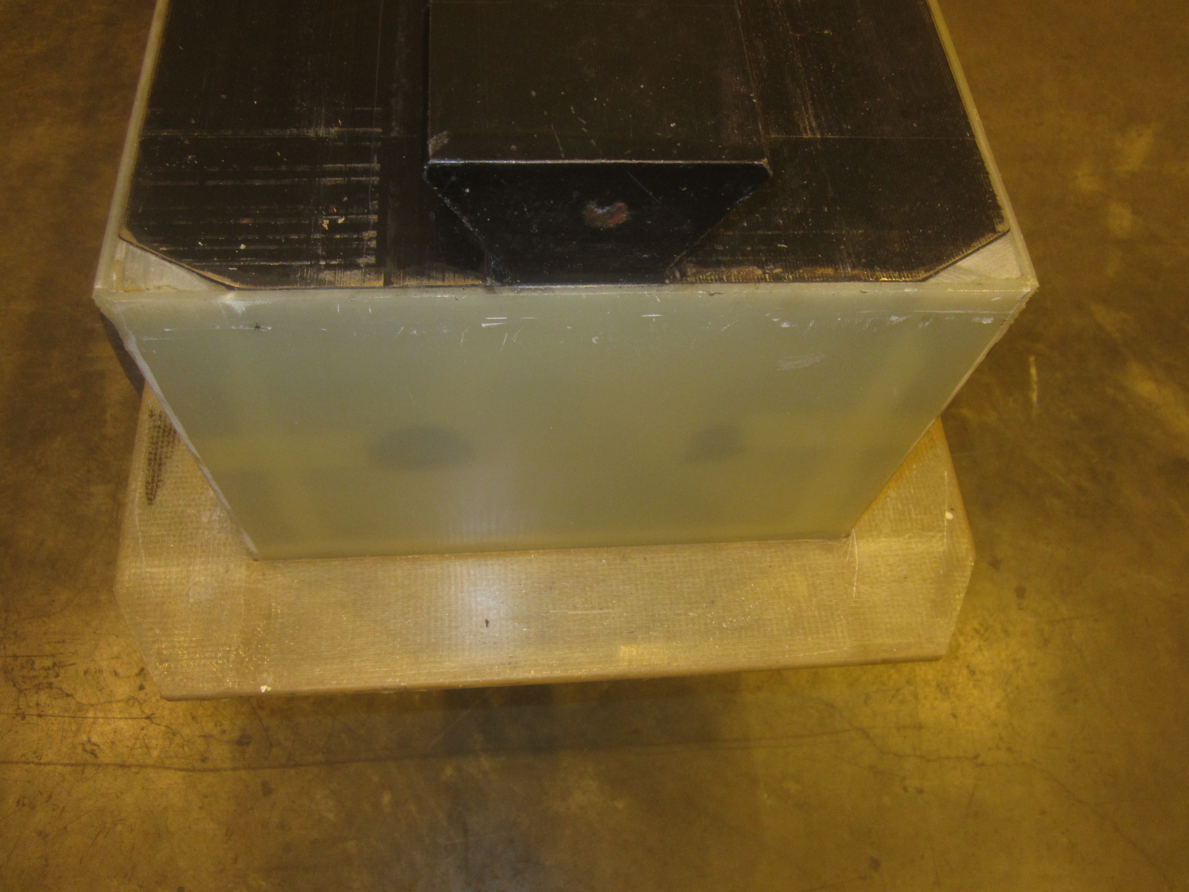
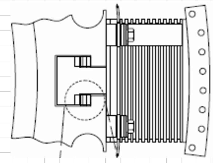
Figure 4: Illustration of typical tee and tee slot arrangement.
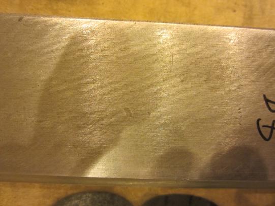
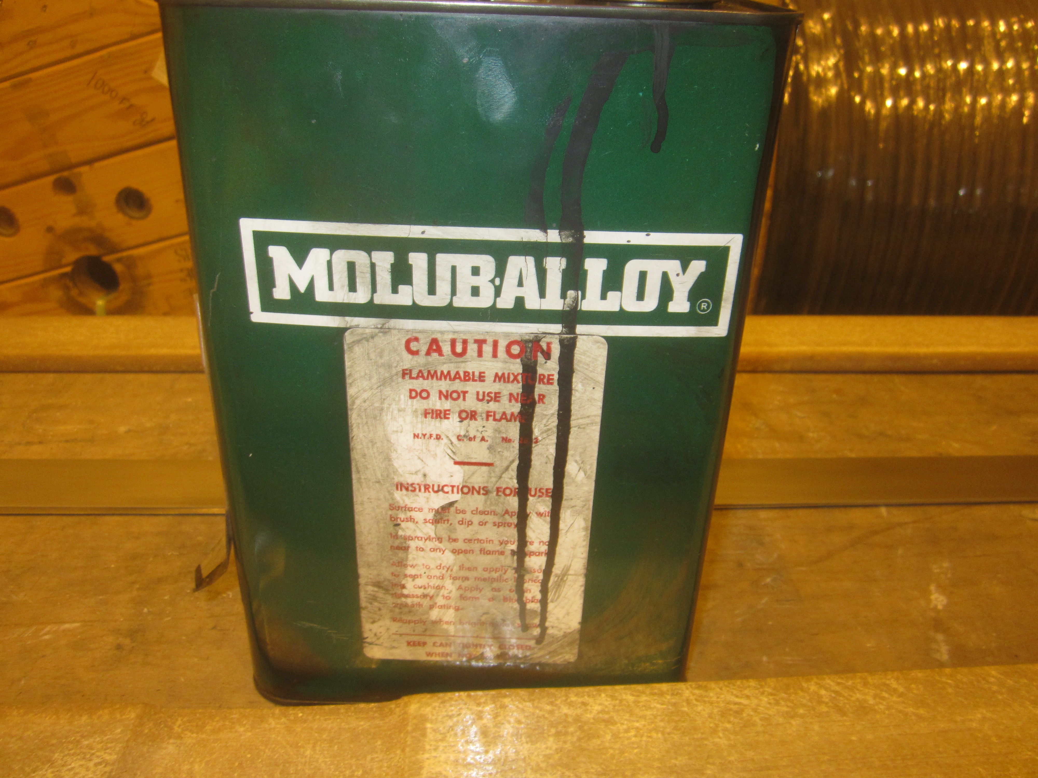
Figure 5: Photo of typical tee and tee slot arrangement. Note the placement of the duplex pole key wedges. D) Coefficient of Friction between the Pole Key Wedges and Wedge Finish There are different opinions regarding pole key lubrication during installation. Lubrication allows the wedges to be driven against each other more efficiently. The further the driven wedge is pushed into the rotor rim slot, the greater the normal force and holding force that is produced. Since it is the frictional force between the outside (non-angled) surface of the keys and the rim slot/pole head that holds the pole in place, theoretically both wedges are prevented from moving and loosening up. Too effective a lubrication could allow the pole keys to create so much lateral force that the rim slot could be over stressed and crack. Not enough lubrication could prevent enough frictional force to be created. The pole could drop down damaging its connection to the adjacent poles or drooping out of the rotor and creating a catastrophic failure of the generator. It was common practice to lubricate the hardened steel keys between the opposing faces of the wedges with Molykote. More recently, the surface of one wedge is plated with softer metal such as tin. The keys are inserted without additional lubricant and driven to refusal. Similarly, surface finish of the pole key wedges needs to be smooth enough to allow the wedges to create a sufficient frictional force while remaining rough enough to create an overlapping lock. As measured surface finishes, with a digital profilometer ranged from 16 to 56 microns. See Figures 6 through 8.
Figure 6: Smooth surface finish of hardened steel pole key. Finish ranged from 23 microns to 44 microns.
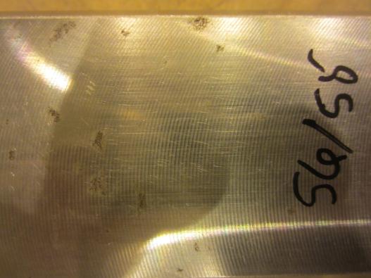
Figure 7: Circular hatching finish of pole key. Finish ranged from 53 microns to 56 microns.
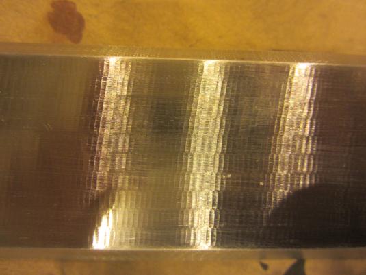
Figure 8: Fish scale finish of pole key. Finish ranged from 16 microns to 30 microns.
Figure 9: Pole keys cleaned and coated with lubricant ready for installation.
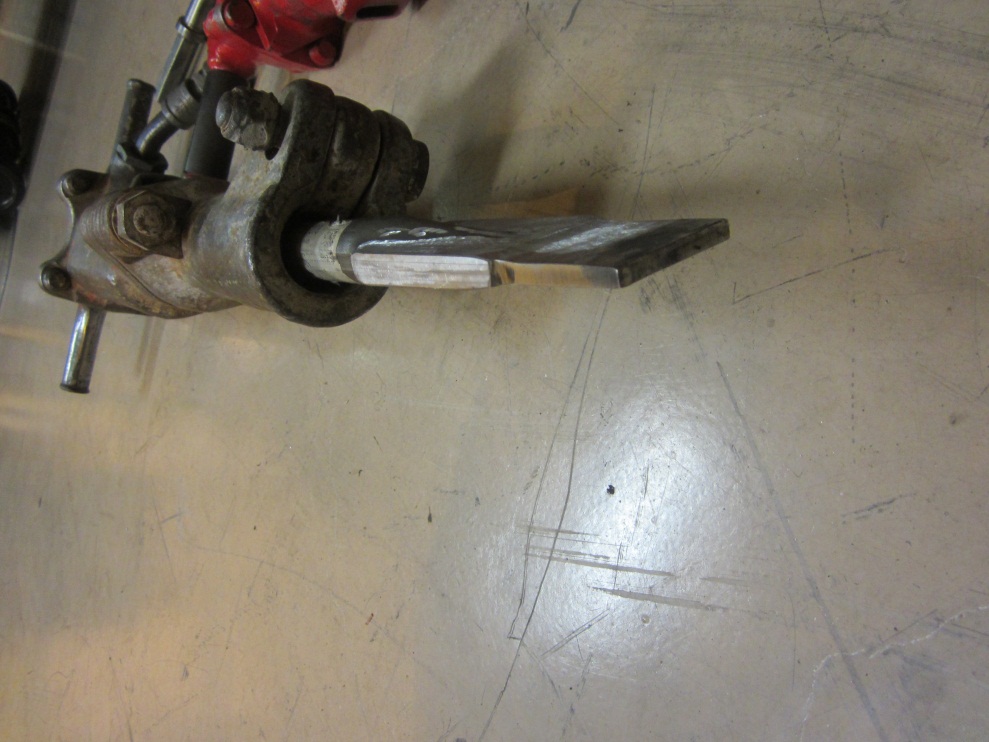
Figure 10: Typical pole key lubricant, extreme pressure, molybdenum disulfide, based grease. It is common practice to drive the keys to refusal. This is defined as the depth the pole key wedge sinks while being driven with sufficient force to a point where there is no further movement. A primitive historical test of this condition is to tap the end of the pole key with a ball peen hammer and listen to the noise. If it" thuds" the pole is not tight enough. It rings like a church bell it is sufficiently tight. D) General discussion of pole key extraction methods The pole keys can be removed by driving the "upwards facing" wedge down or by pulling the "downwards facing" wedge up. The wedge can be driven down with a hammer or a pavement breaker. During downward driving, a special chisel is ground whose end matches the width and thickness of the small end of the pole key wedge. If a pavement breaker is used a pavement breaker is ground so that its end matches the width and thickness of the small end of the pole key wedge. A support, such as a small hydraulic jack is placed beneath the upwards facing wedge to prevent it from moving while its opposing wedge is driven down.
Figure 11 : Pavement breaker with ground chisel used to free pole key wedge by driving it down.
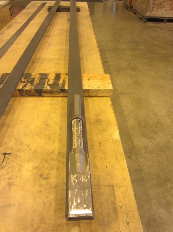
Figure 12: Comparison of thin edge of pole key wedge and ground macadam chisel. Alternatively, the wedges are sometimes pulled upwards by the use of an extraction tool. On the smaller machines a slide hammer is welded to the large end of the downwards facing pole key wedge. For larger machines, a large diameter threaded rod has flats machined on one end. The remaining rectangular tongue matches the rectangular dimension of the large end of the downwards facing pole key wedge. The threaded rod is welded to the wedge. A suitable jacking column, such as a large piece of pipe is slid over the threaded rod. The pipe inside diameter must be large enough to accommodate the wedge. A special, thick washer is slid down the threaded rod. The washer should be large enough to cover the top of the jacking column. A nut and wrench or a hollow core hydraulic cylinder is used to extract the pole key wedge out of the dovetail slot.
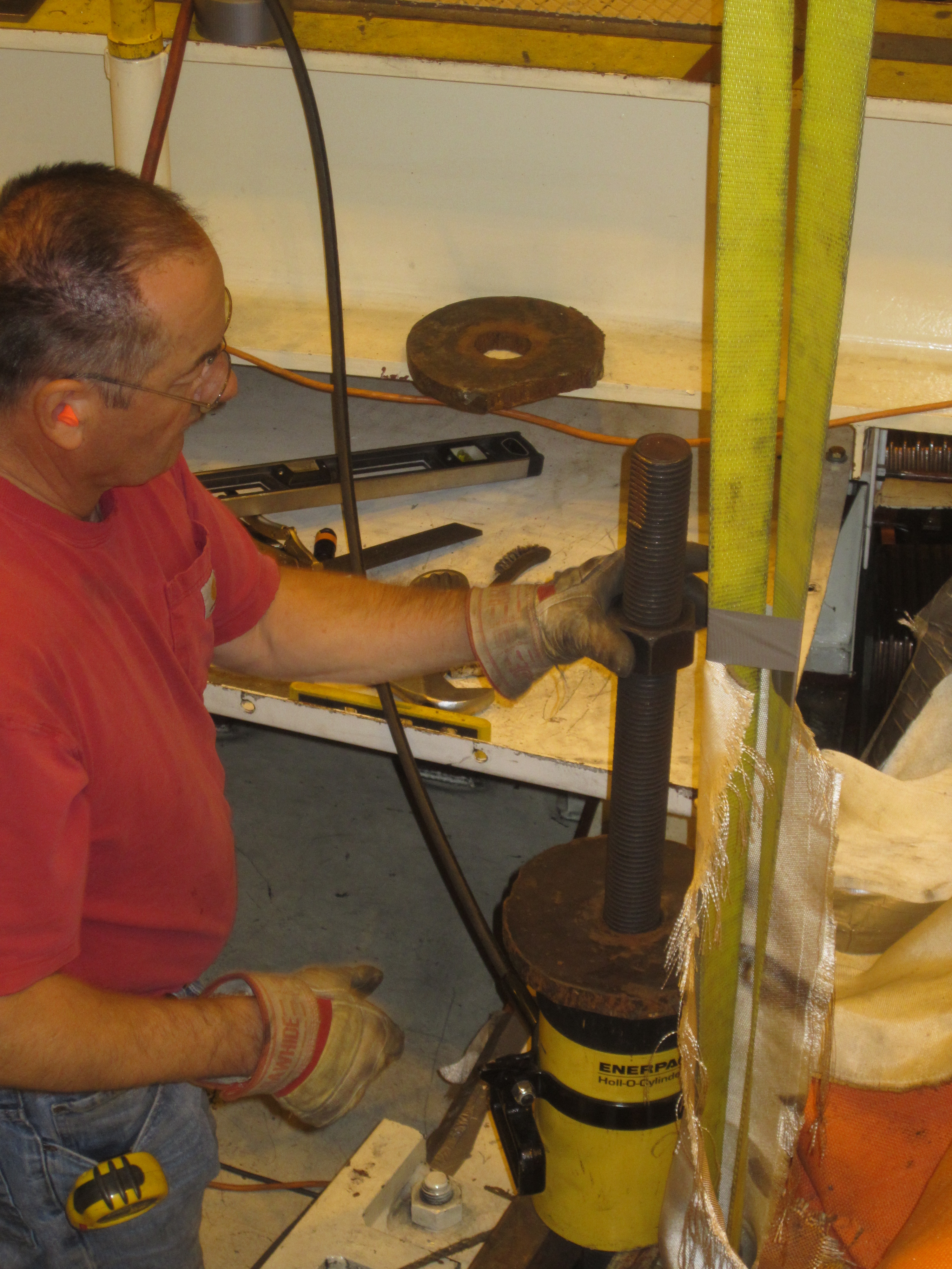
Figure 13: Hollow core ram and 1 1/2 inch diameter threaded rod being used to jack up the pole key wedge.
Figure 14: Threaded rod and nut still welded to a piece of pole key wedge. Alternatively, if the pole key wedge projects far enough above the rotor rim and its opposing wedge, a Tee bar can be welded across its top. The loops of a lifting strap can be slipped over the ends of the bar. The bridge crane can be used to pull the pole key wedge.
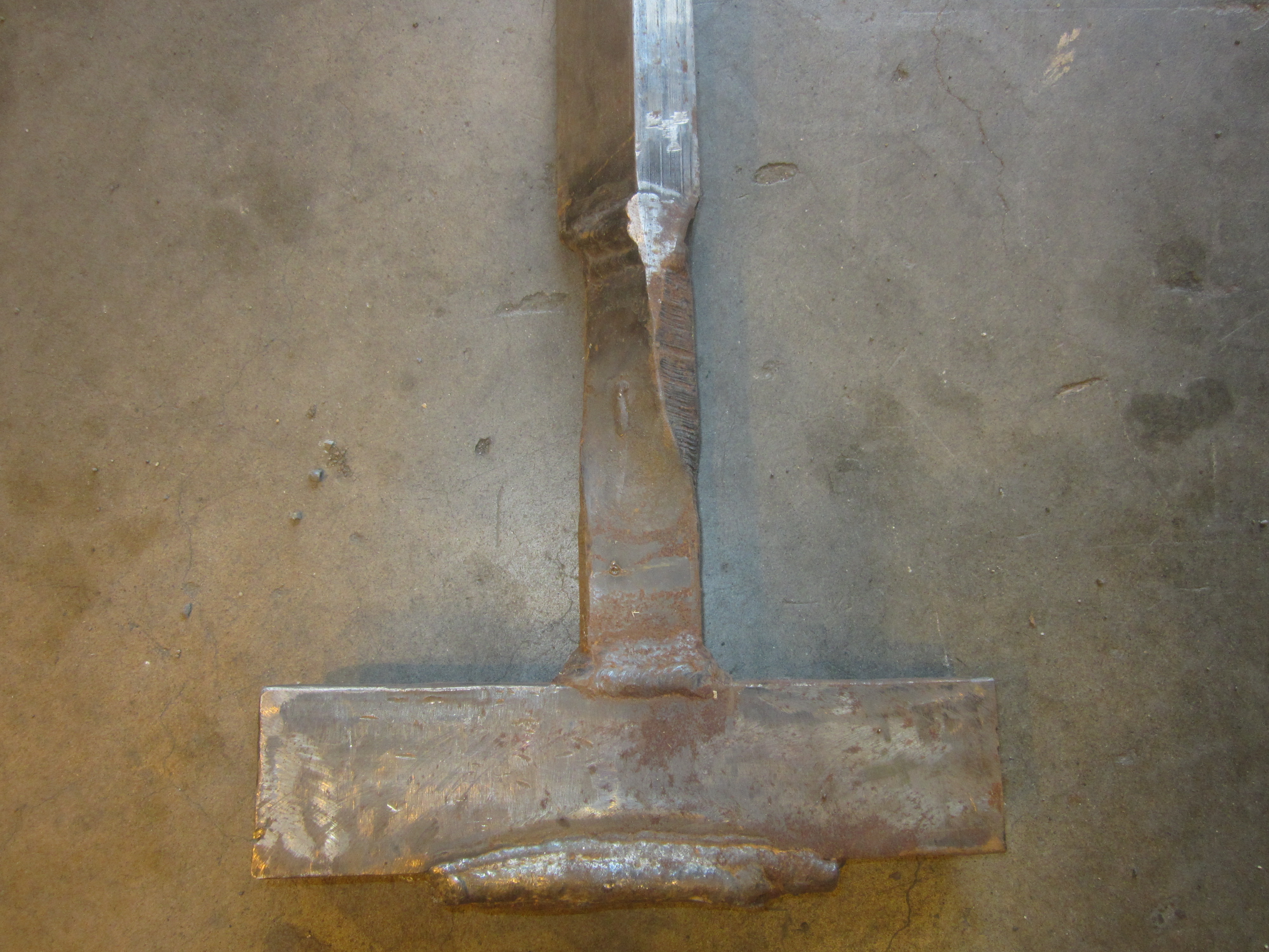
Figure 15: Tee bar welded to end of pole key wedge.
Figure 16: Close up of Tee bar welded to end of pole key wedge.
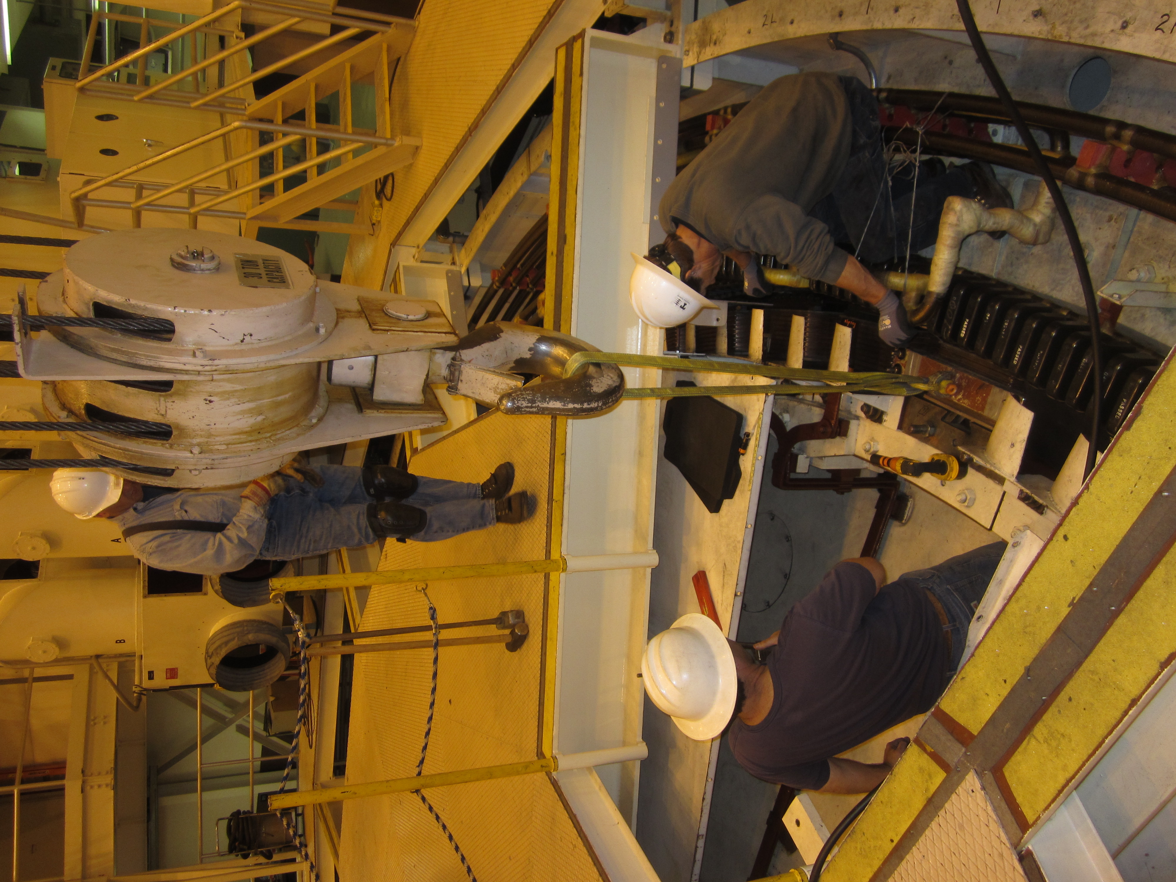
II) ASEA Pole Extraction: One of Tacoma's units was exhibiting signing of fretting. The fretting dust was found on the outside of a number of rotor poles. It was decided to remove the pole and inspect it during an annual outage. The following photos demonstrate the process used to extract the pole keys and remove the pole from the unit.
Figure 17: The pole lifting fixture has been affixed to the pole body. The fixture has been attached to the bridge crane with a lifting strap. The pole has been lightly loaded to prevent it from dropping when the pole keys are loosened.
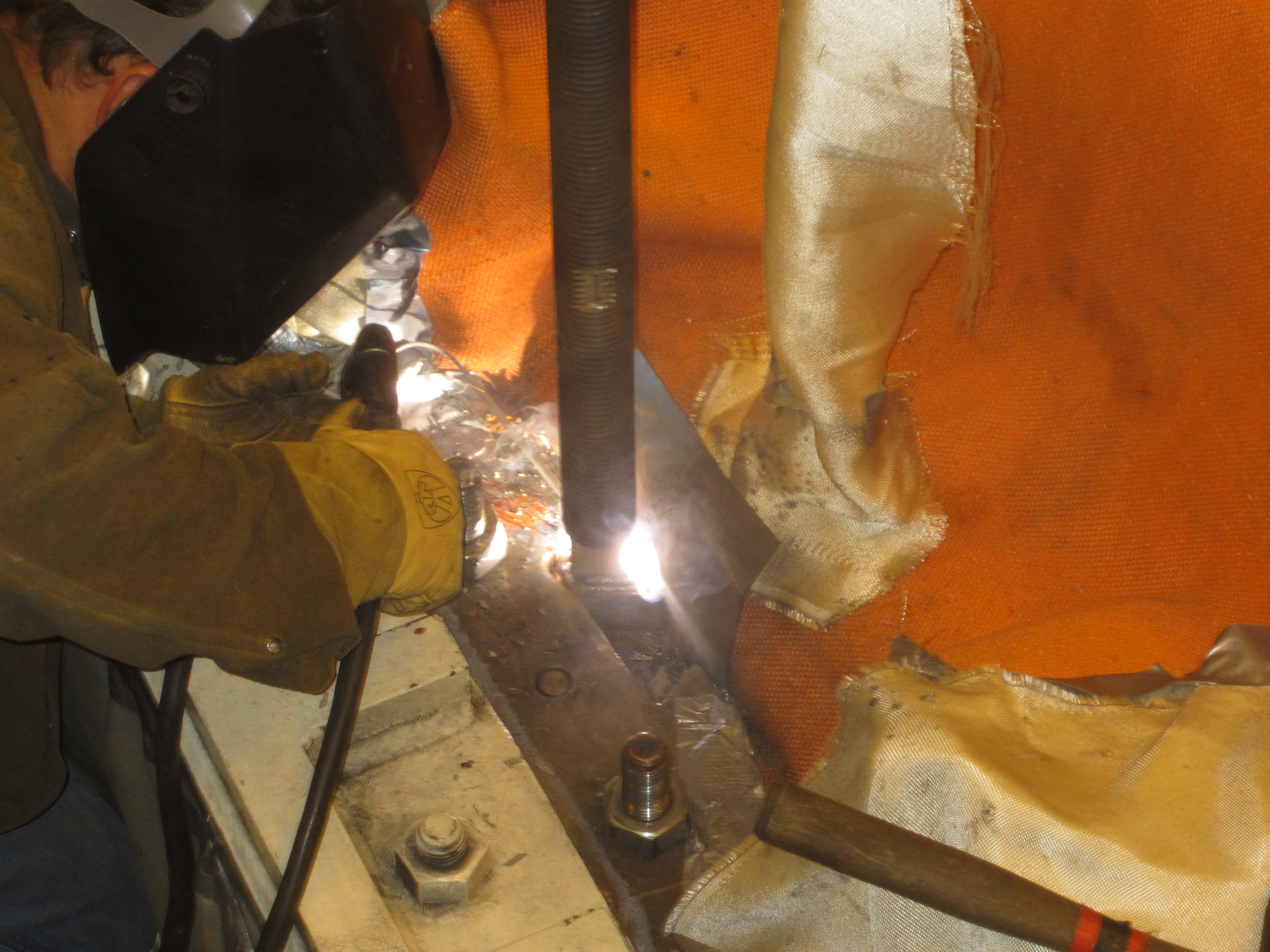
Figure 18: Welding the threaded rod onto the top of the pole key wedge.
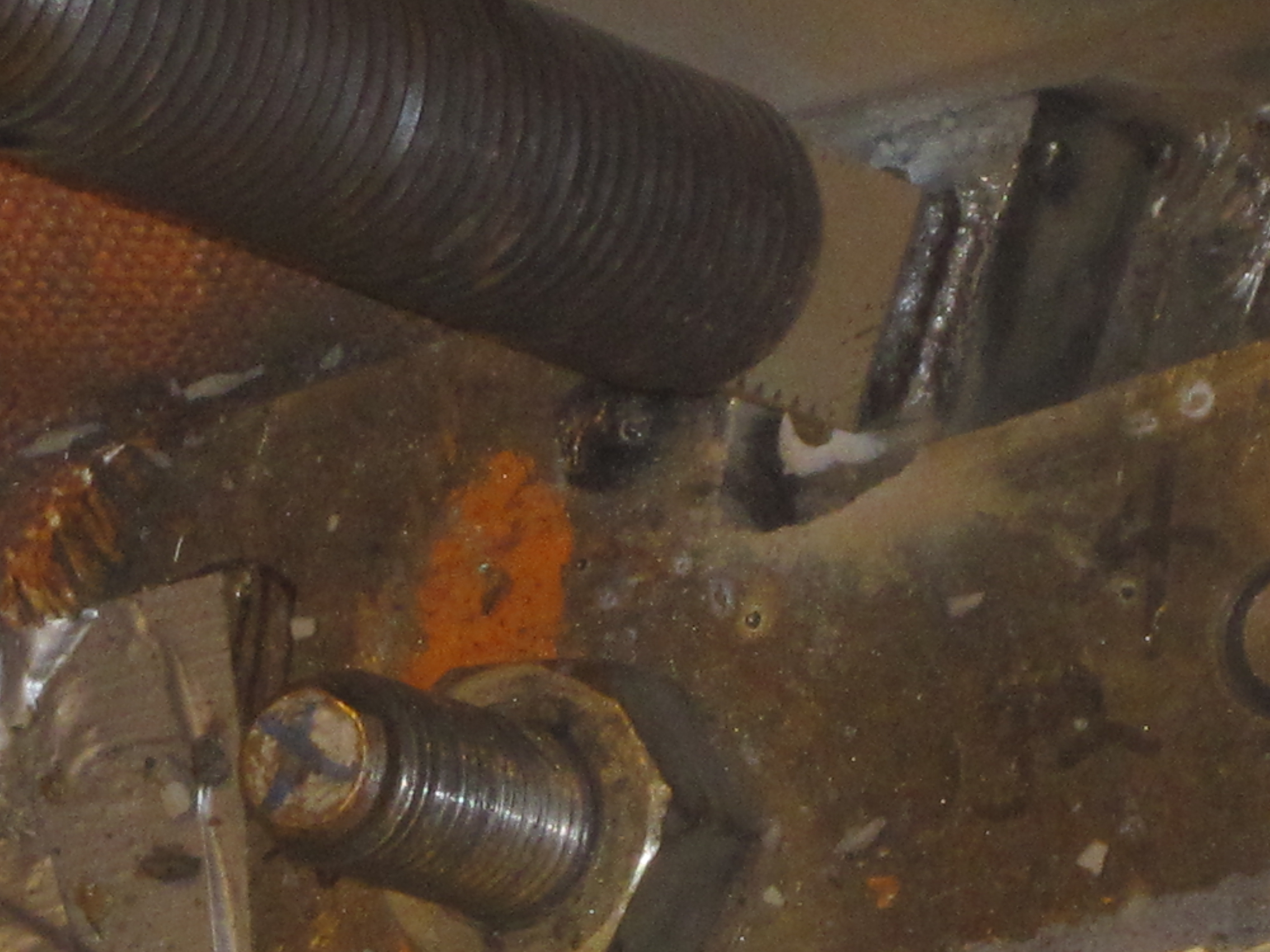
Figure 19: The 1 1/2 inch pole extraction threaded rod welded to the wedge ready to start the extraction..
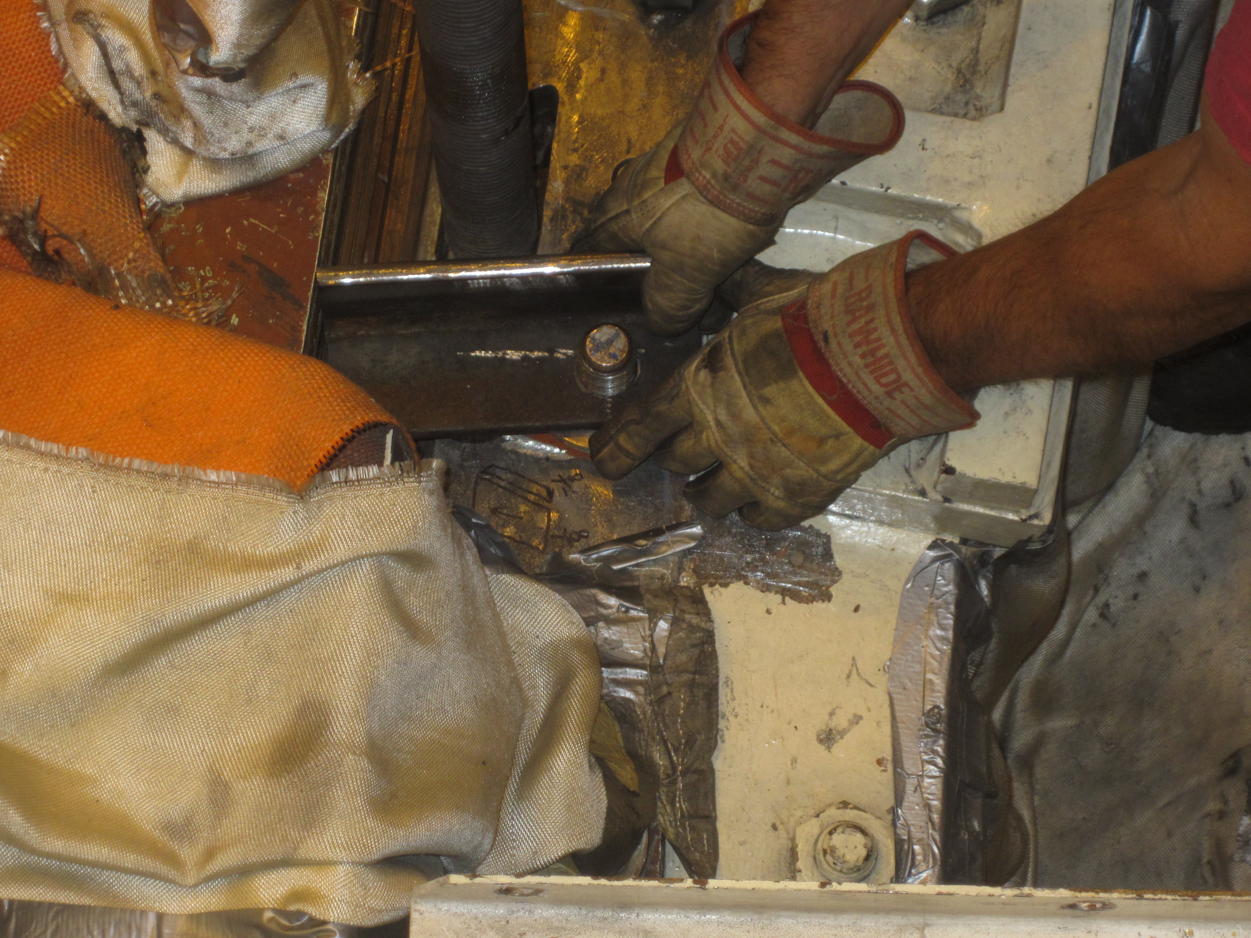
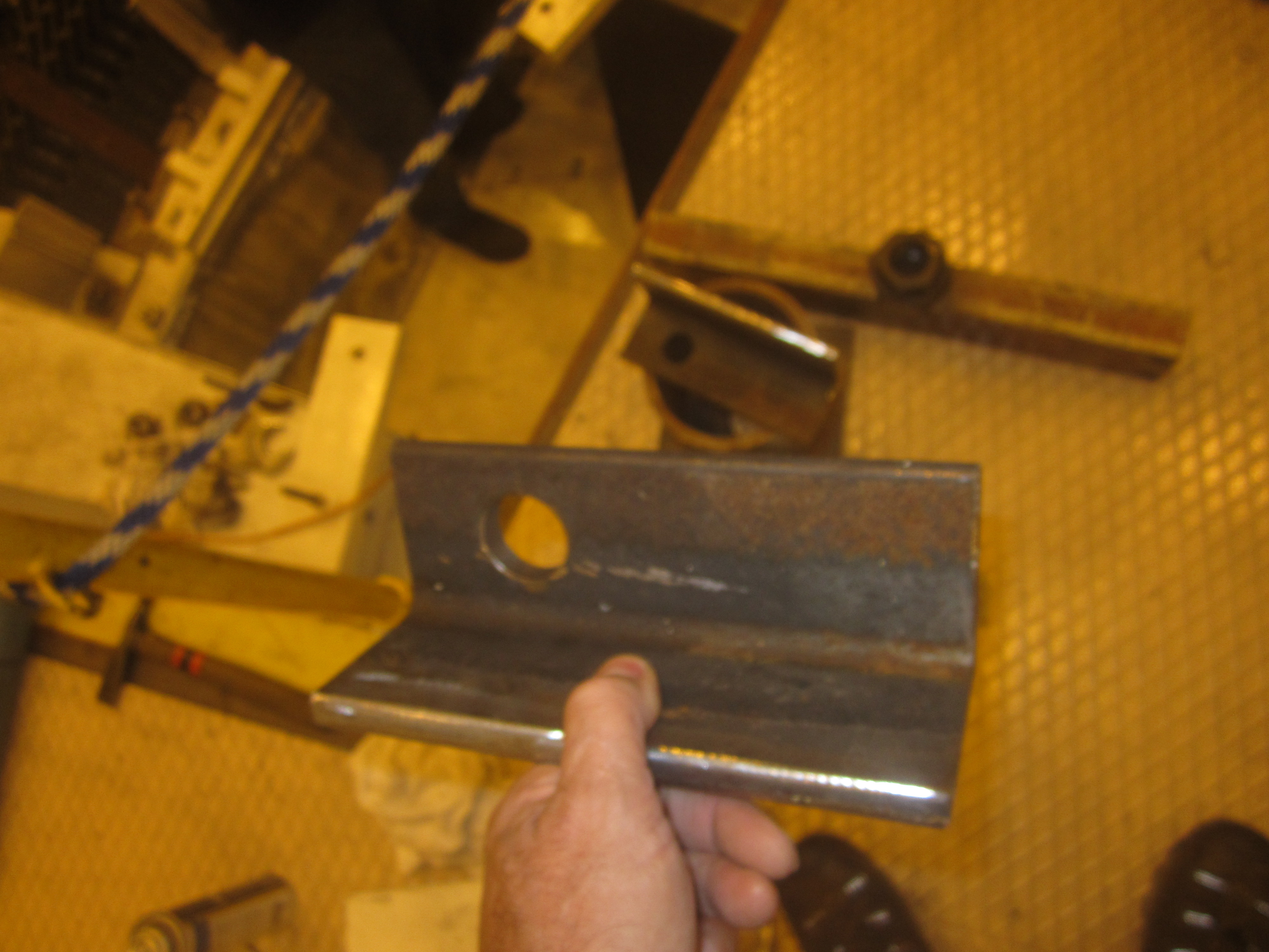
Figure 20: The cantilevered jacking foot is slipped over a rotor rim lamination pinch stud.
Figure 21: The 1 1/2 inch threaded jacking rod has been welded to the top of the pole key wedge. Two rim lamination compression nuts have been removed and cantilevered jacking feet are being installed to allow the centerline of the hollow core jack to be supported when it is slipped over the jacking rod.
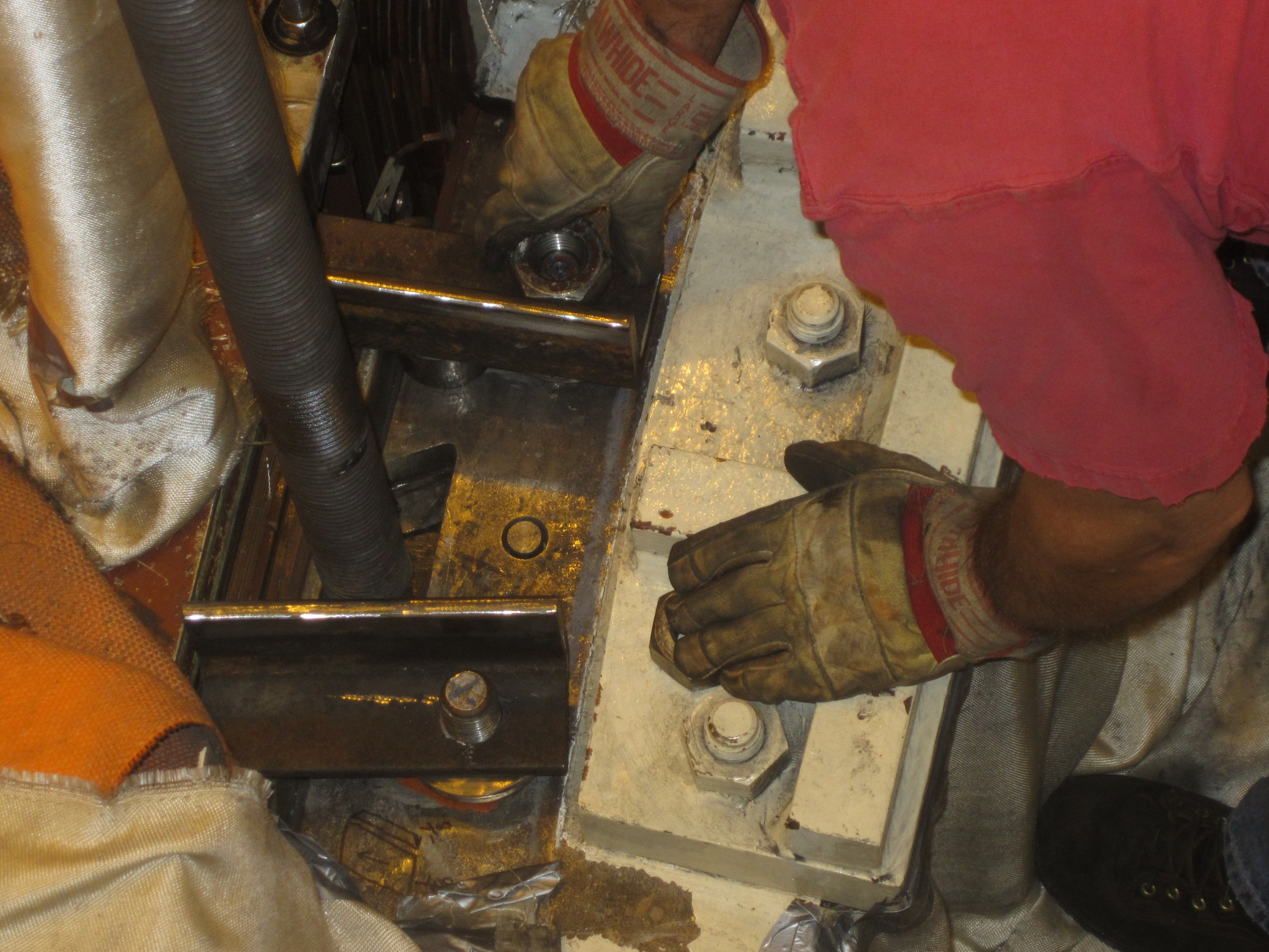
Figure 22: Two foundation columns are slipped beneath the jacking footings.
Figure 23: Two foundation columns.
Figure 24: Cantilevered soft jack footing.
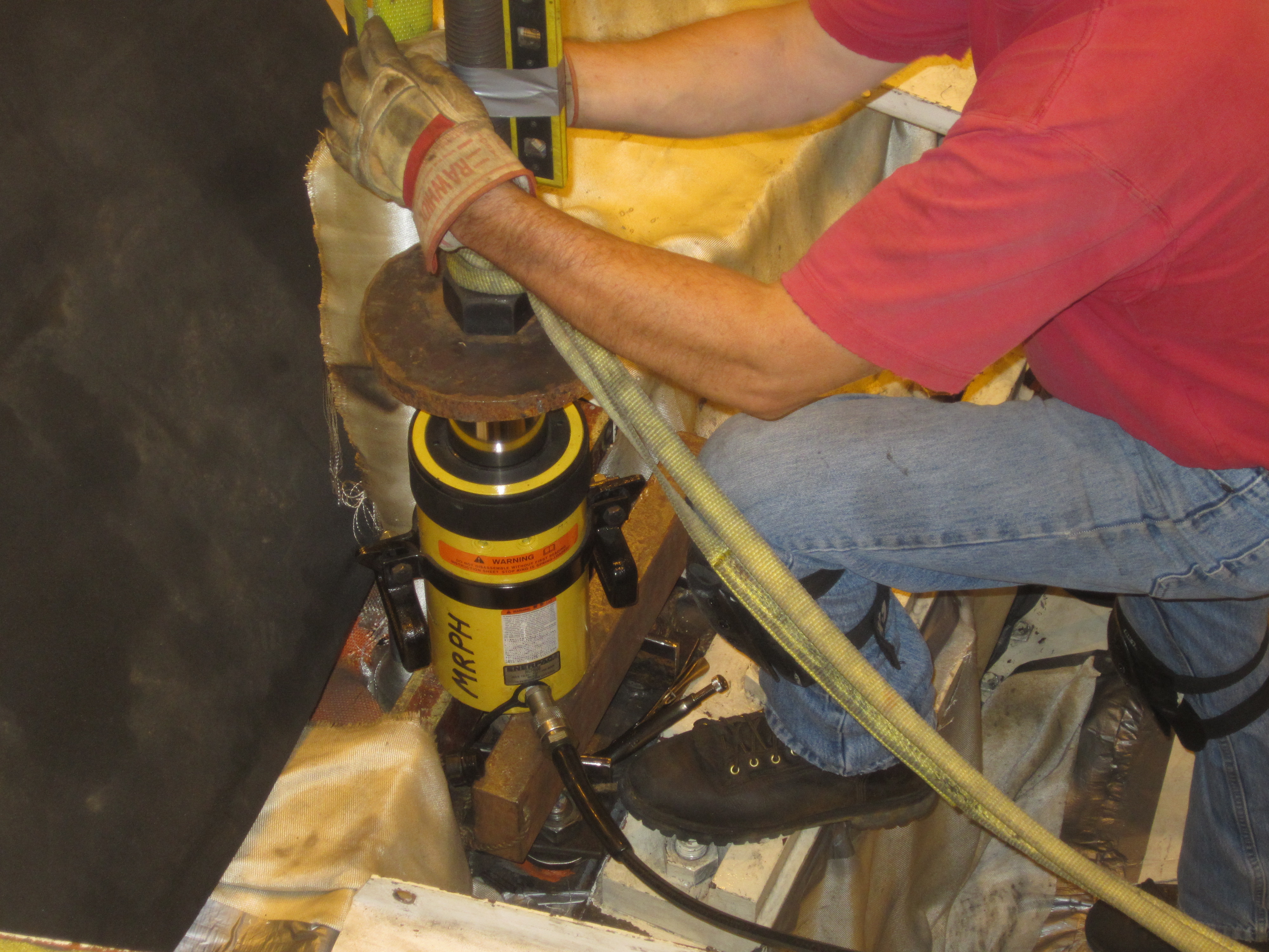
Figure 25: The hollow core ram and the heavy thrust washer have been slipped over the threaded jacking rod and the jacking nut is being spun down the rod.
Figure 26: Because the cantilevered jacking footing is "soft", a torpedo level is being taped to the rod to see if it tilts. The cum-a-long is holding the top of the rod to prevent tilting. The direction of the pulling force is kept vertical but a large moment results in the weld between the threaded rod and the wedge.
Figure 27: The hollow core ram is being pressurized with the foot valve.
Figure 28: The hollow core ram has pulled the wedge out.
Figure 29: The "prize". The pole key wedge is carried away. Note the 1 1/2 inch threaded rod welded to the top of the wedge.
Figure 30: The pole is extracted from the dovetail slot in the rim.
Figure 31: The pole is fully extracted.
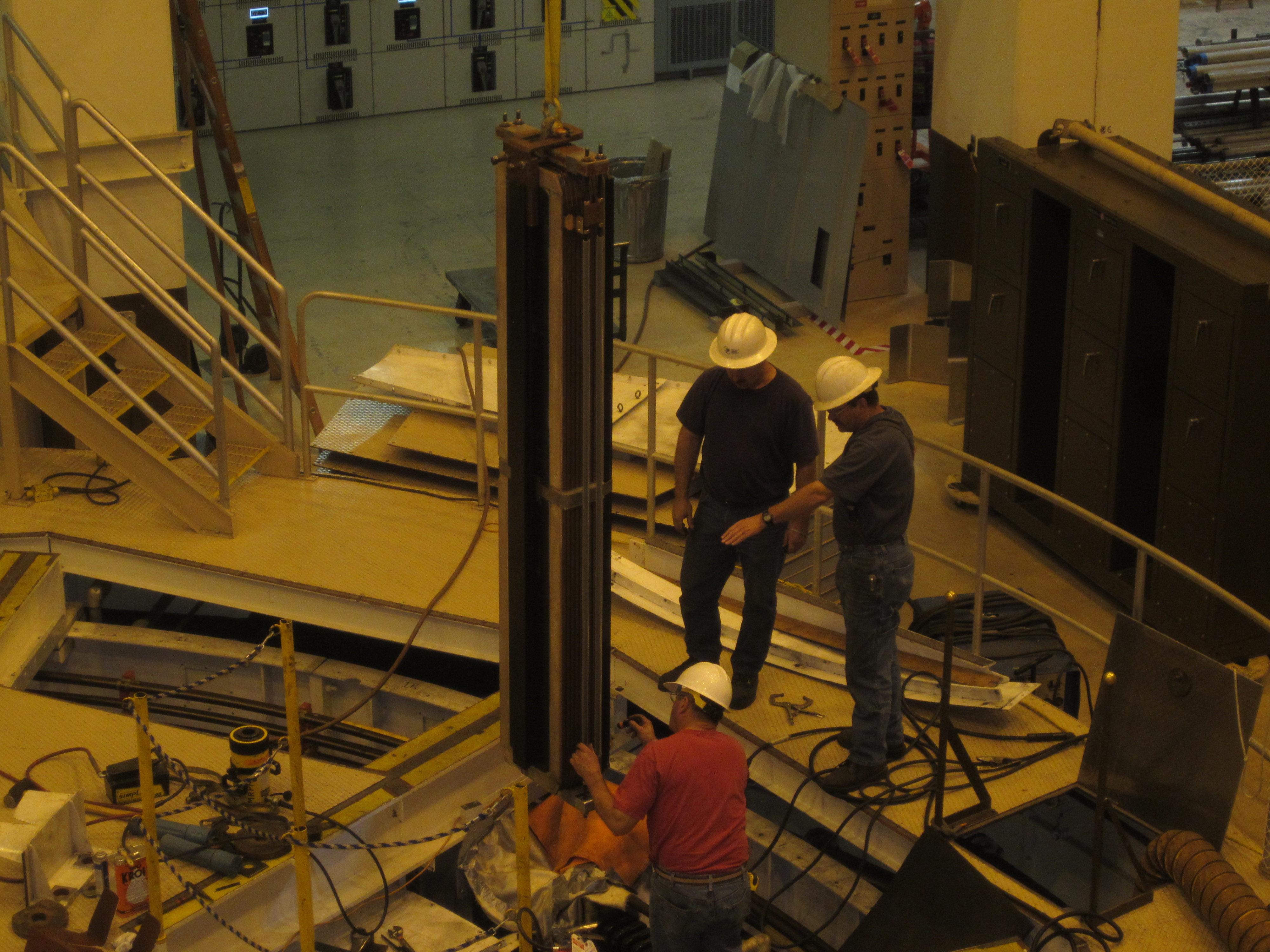
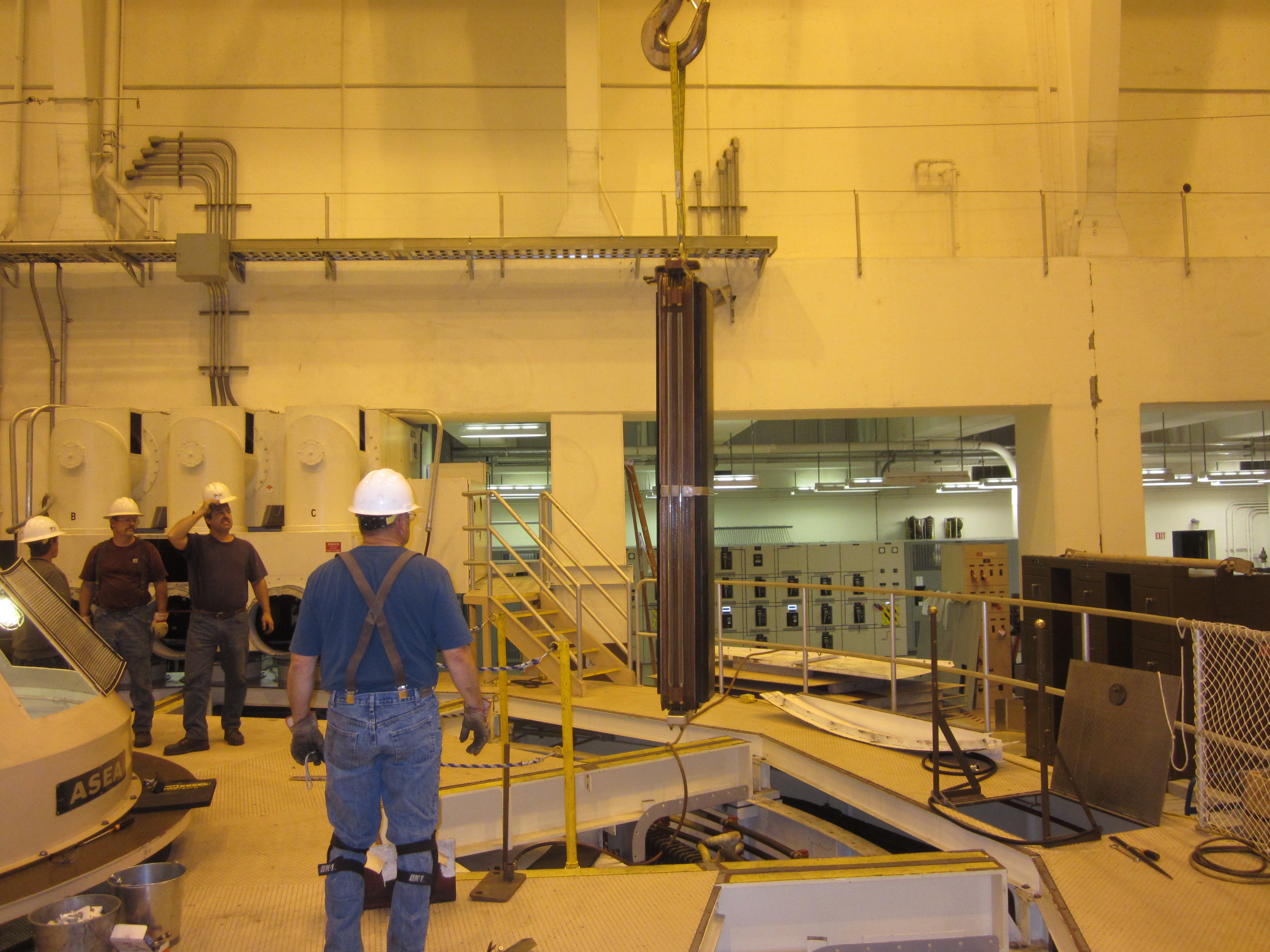
Figure 32: The pole is being "flown" to its cradle using the bridge crane.
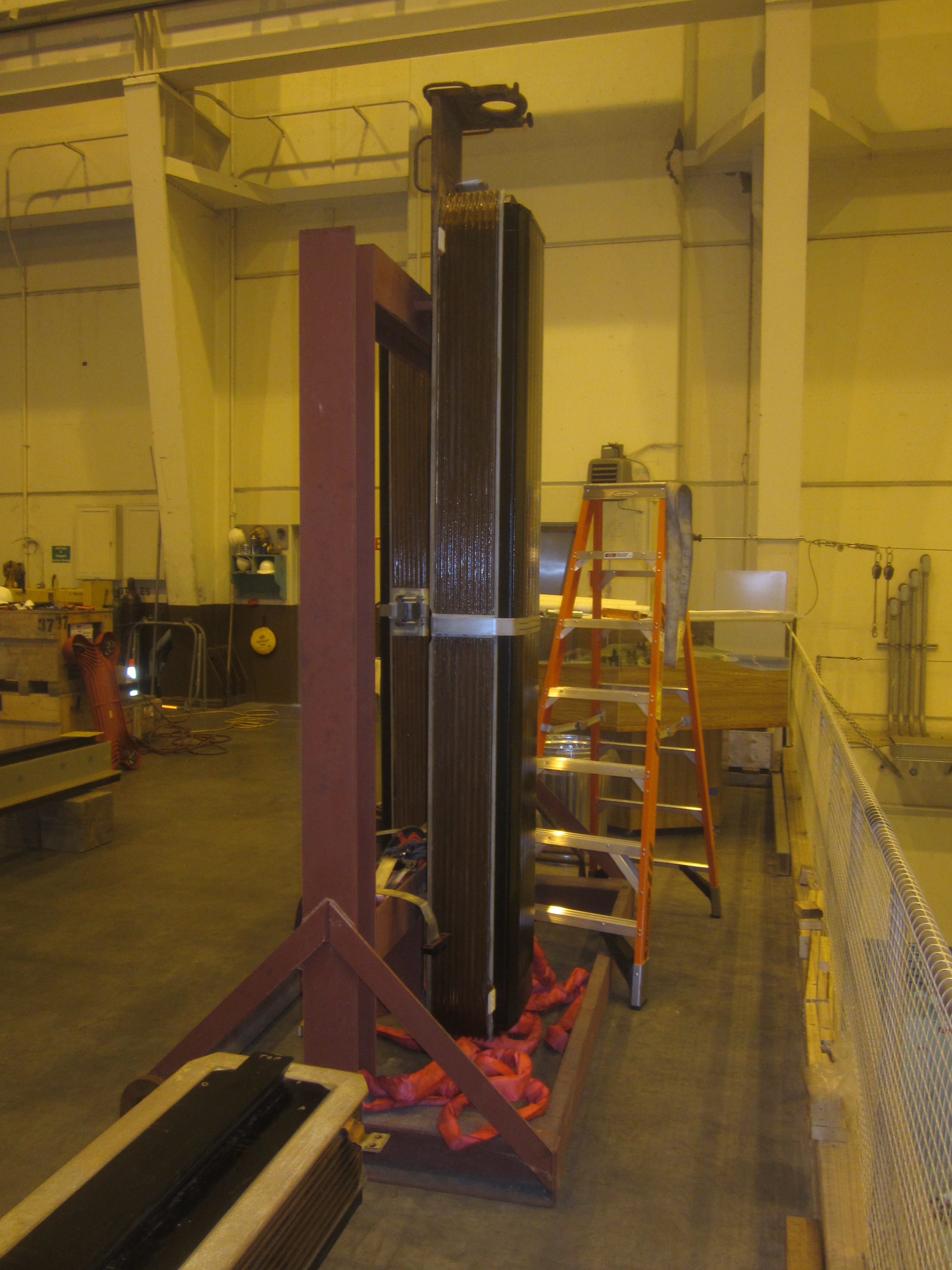
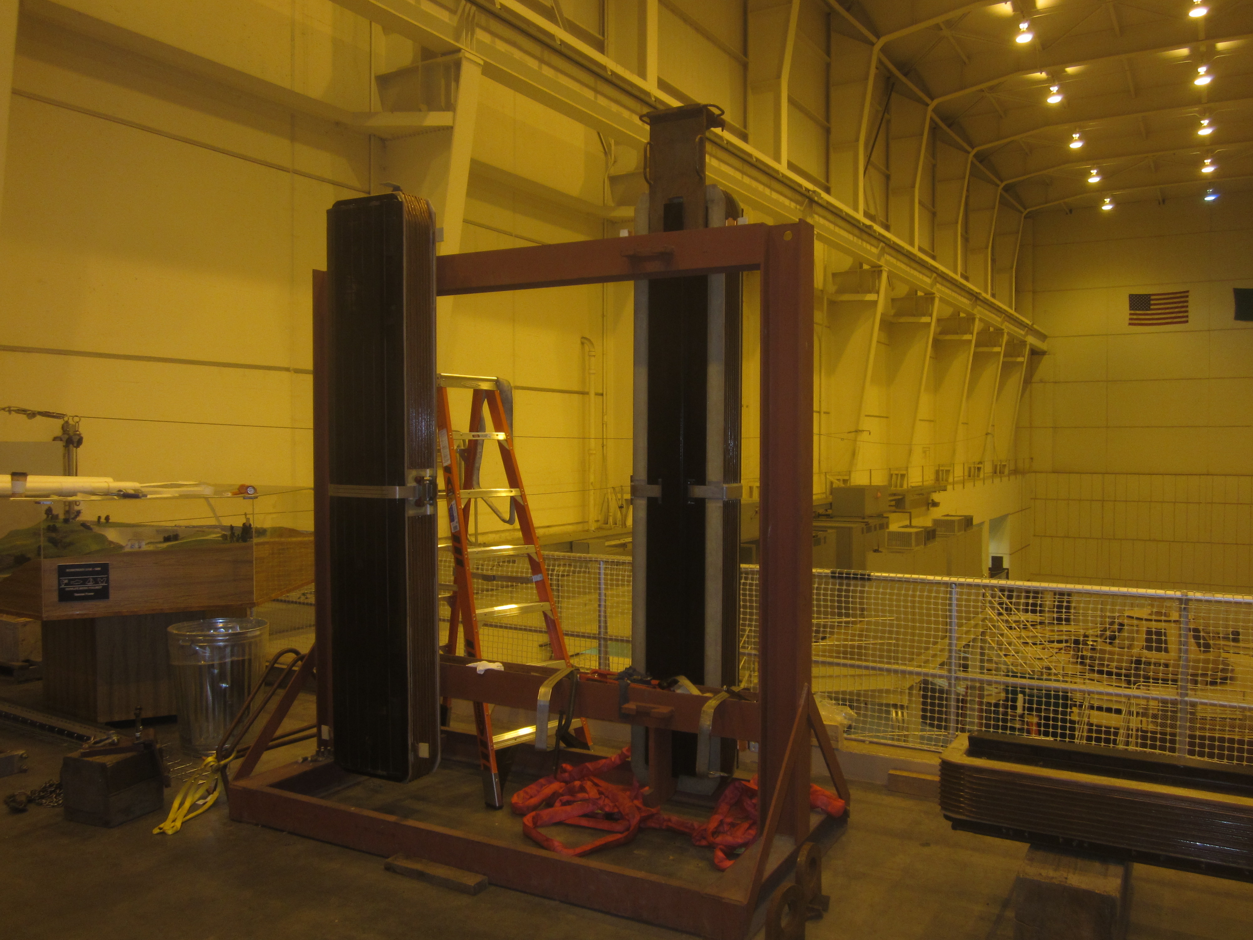
Figure 33: The pole secured in the storage rig for future inspection.
III) ASEA Pole Installation:
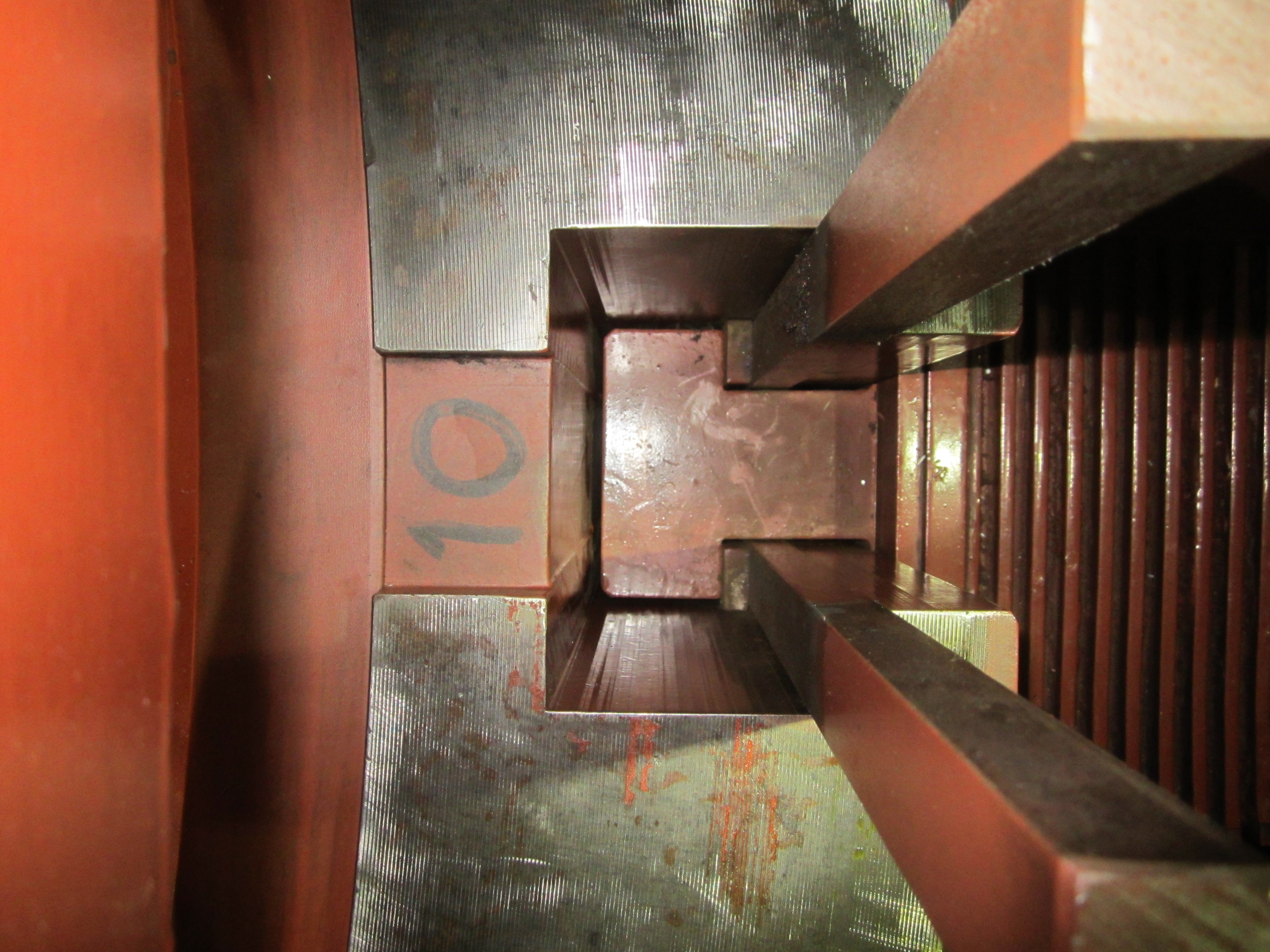
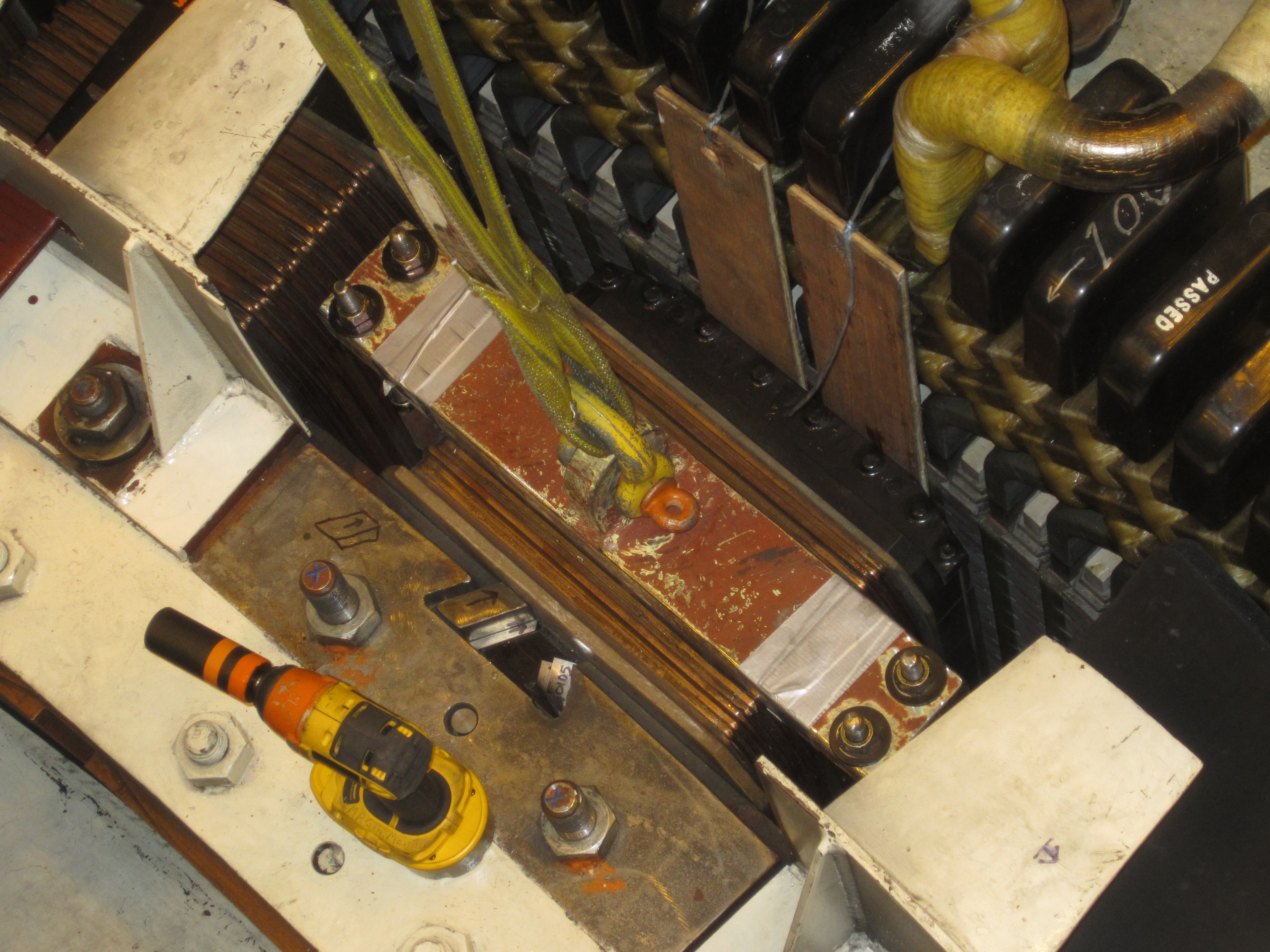
IV) Electrosila Pole Extraction: At Tacoma's Wynoochee HEP during reassembly, after the runner blades were centered in the throat, air gap readings were taken to determine if the rotor was centered in the stator. The readings were non-uniform from pole to pole. It was also noted the lower air gaps were universally lower than the upper air gaps. Pole 10 exhibited the most extreme air gap readings. These conditions can be the result of loose poles. The ends of the opposing wedges were checked for tightness. The upper ends were extremely tight. The lower ends could be moved by hand. It was decided to pull pole ten to ascertain the condition of its anchoring surfaces and wedge pairs. The poles would be observed for fretting or other unusual marks. The surfaces of the tapered keys would be scrutinized for fretting, galling and machining marks. Removal: The original Russian pole wedge removal tool was located. The tool consists of a cylinder with a pulling ring welded to the top. Two tapered jaws are fitted to the inside of the cylinder. The tool is positioned on the large end of the wedge. As it is pulled upwards, the jaws contract onto the wedge which allows it to be pulled upwards. The cooling fan was lifted up on cum-a-longs and pulled sideways to expose the top of the pole piece and the two sets of protruding wedges. The interpole connections were a mechanical design. They were not soldered or brazed together. They were disconnected. The pole removal device was hung from a 3 ton chain cum-a-long that was attached to the bridge crane. The wedge was loaded with the cum-a-long. It did not move. A port-a-power cylinder was set up beneath the small end of the wedge to break it free. As the wedge was both pulled from the top and pushed up from below it broke free. Once the wedge was extracted the opposing key was retrieved from the wedge slot. The process was repeated for the second pair of wedges. Once the wedges were removed, a 16 foot by three inch strap was wrapped vertically around the pole piece and choked. A ratchet strap was used to wrap around the lifting strap and pole piece to prevent the pole from sliding sideways out of the lifting strap. The cum-a-long was used to slowly load the weight of the pole onto the bridge crane. Once the pole piece lifted free it was removed the rest of the way with the bridge crane. A preliminary inspection of the pole piece, the rotor slot and the wedges was made. The following items were notable: 1. Both the spare wedges and the wedges that were removed had very rough sliding surfaces. There were intermittent wear marks on the wedges that showed they never made full surface to surface contact. 2. There is no indication of fretting on any surface. This indicates a lack of movement of the pole/wedges/rotor slot system.
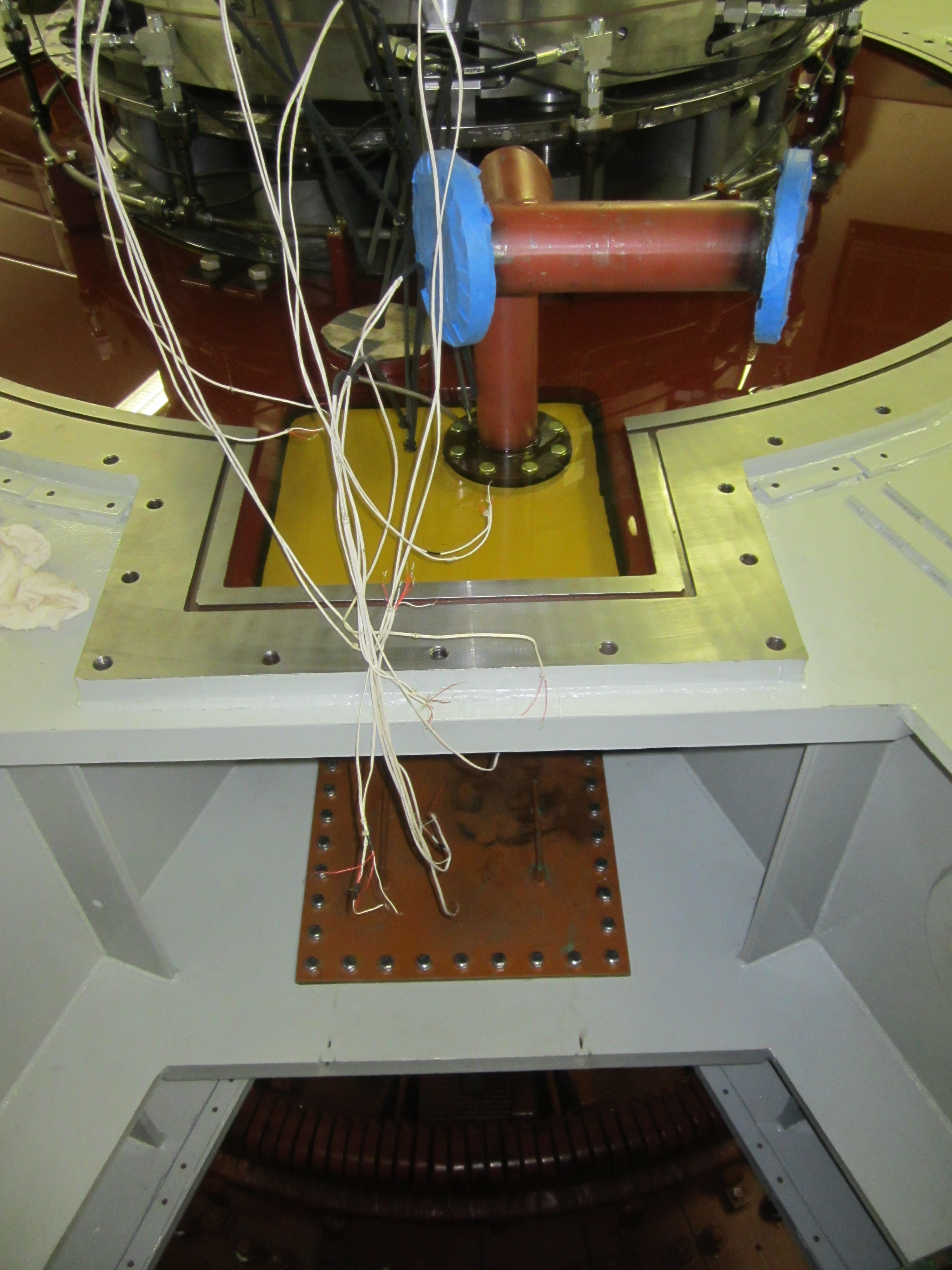
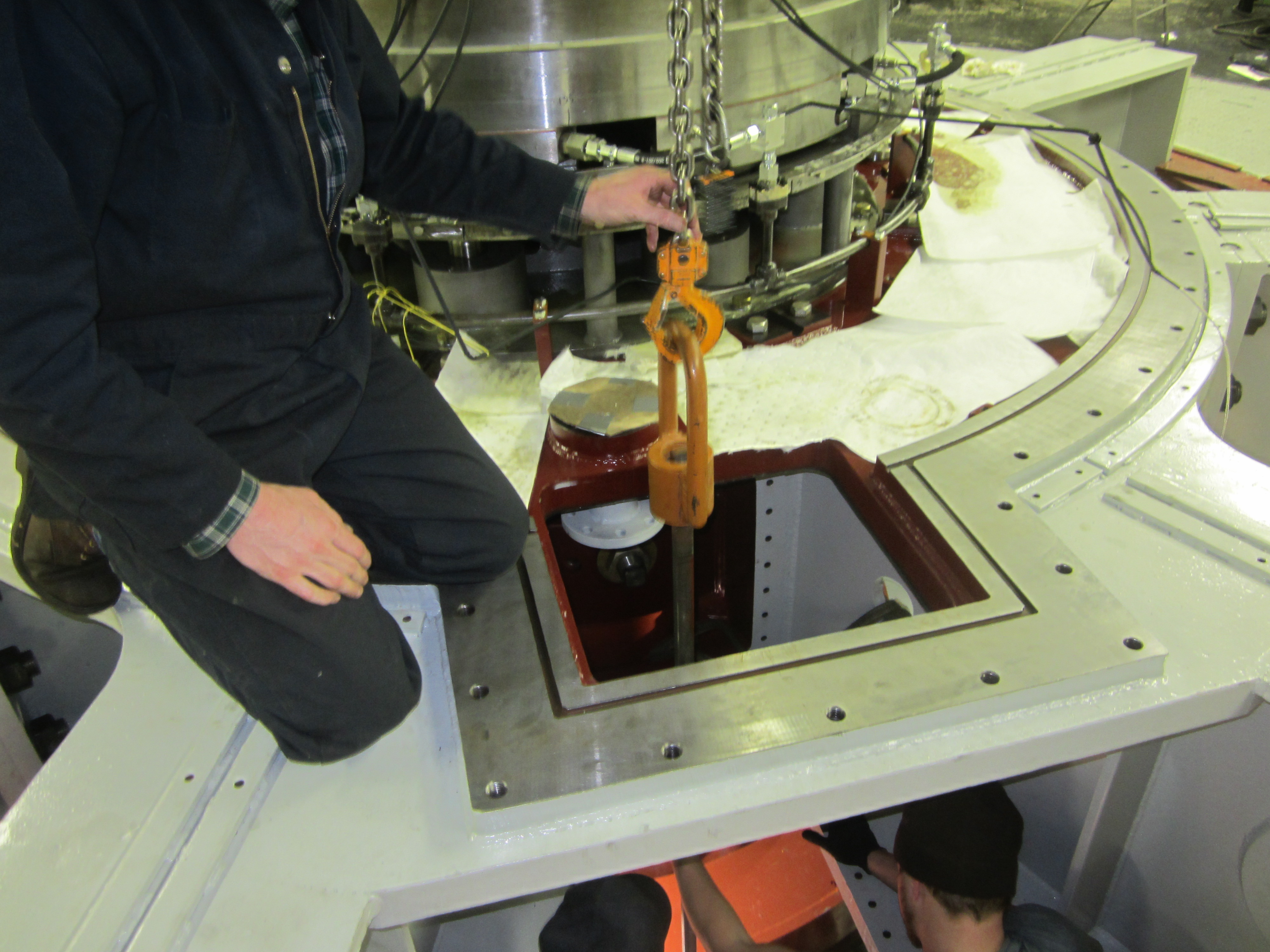
Figure 34-One: Note the two rectangular covers closing off the two rectangular holes in the upper bracket used for pole piece removal.
Figure 32-Two: Original Russian pole wedge removal tool. Note the two serrated jaws used to grip the top of the wedge like a Chinese finger trap.
Figure 33-Three: The heavy duty cooling fan has been detached, elevated and pulled sideways with cum-a-longs to expose the top of the pole pieces and pole piece wedges.
Figure 34-Four: The wedge puller has been lowered over the top of the wedge. The serrated jaws are being set with the ball peen hammer.
Figure 35-Five: After being pulled from the top and pushed from below with a port-a-power, the wedge broke free.
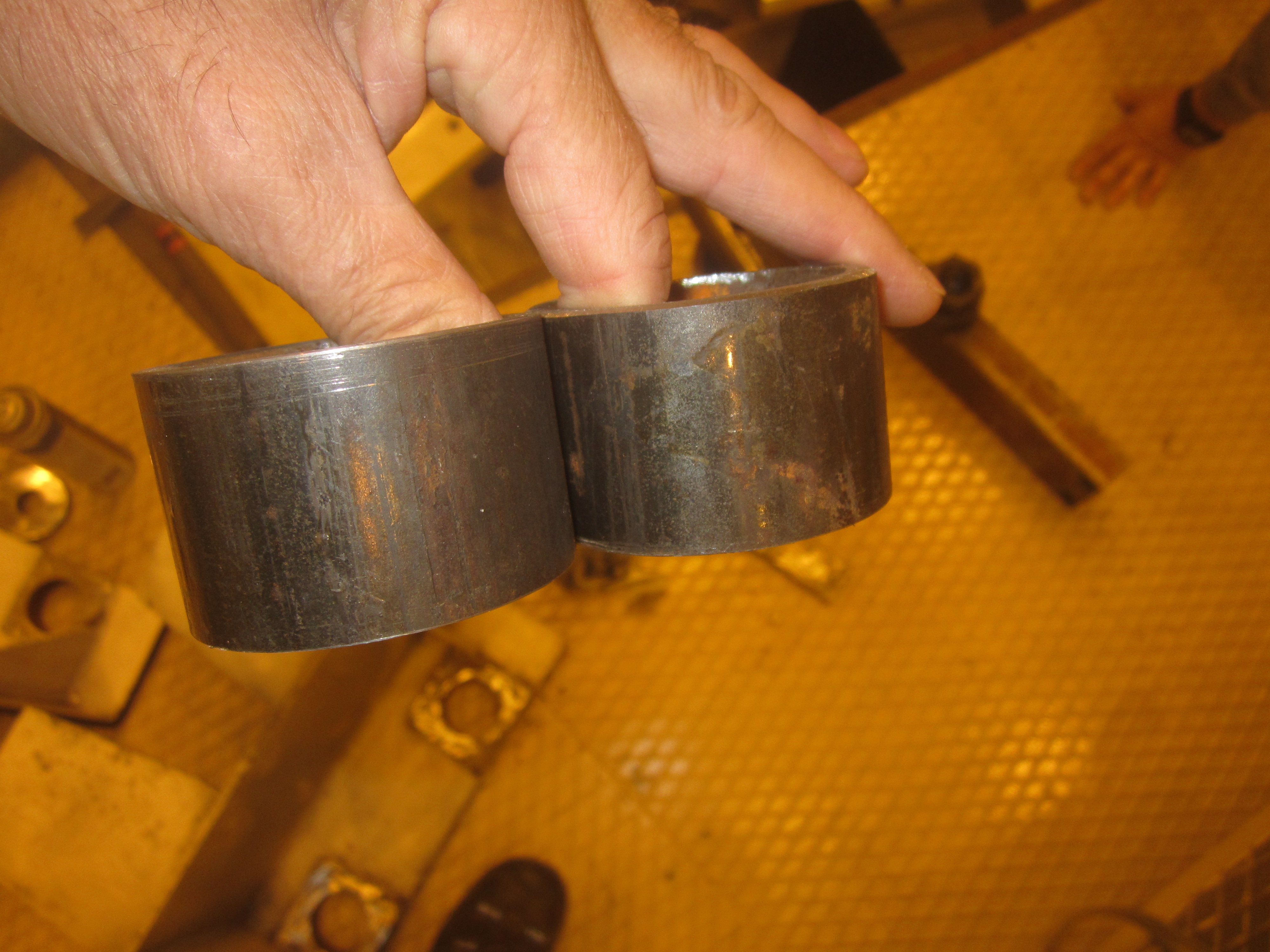
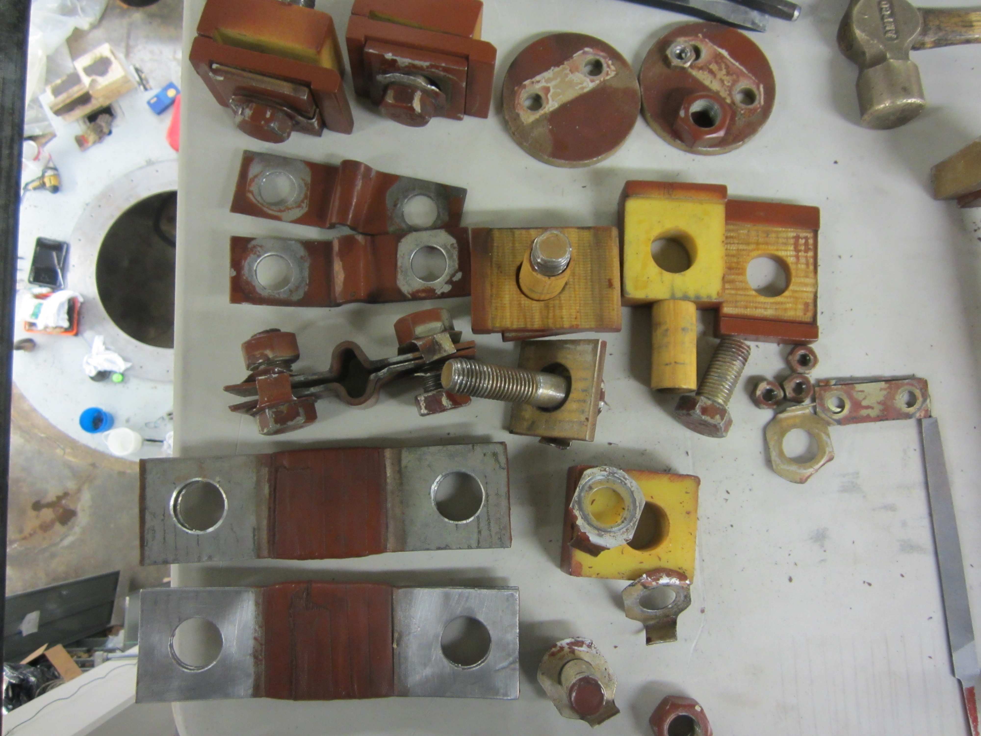
Figure 36-Six: A matched pair of extracted wedges. The longer wedge faced down with its large end up top. The shorter wedge faced up with its large end at the bottom.
Figure 37-Seven: Note the surface marks on the wedge. The black is where it touched the matching wedge.
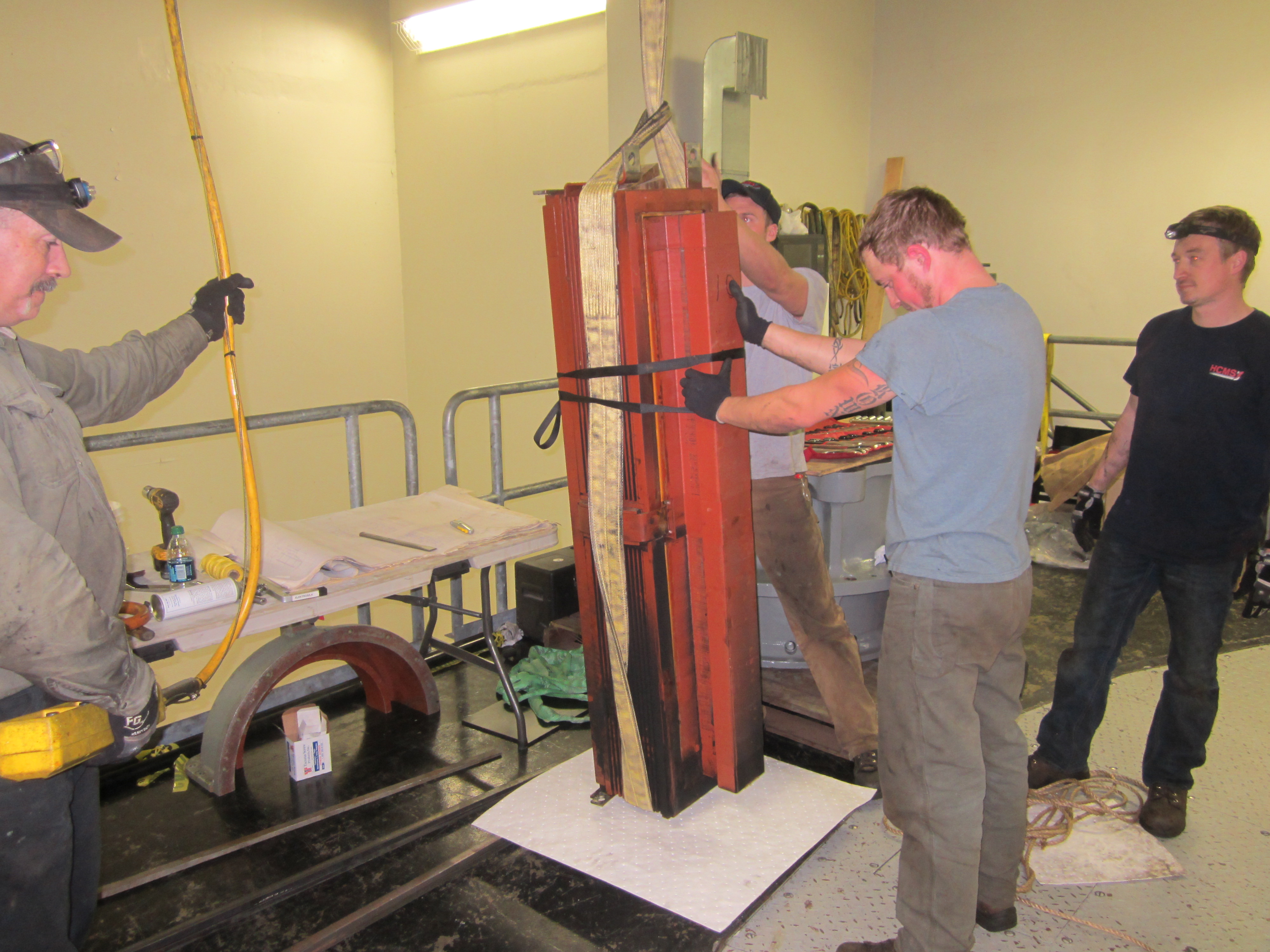
Figure 38-Eight: Choked lifting strap used to lift pole. The mechanic is setting the choke by pushing down on the loop.
Figure 39-Nine: The pole is being lifted up.
Figure 40-Ten: The pole is extracted from the upper bracket through the rectangular port holes provided for its removal.
Figure 41-Eleven: The pole is ready for inspection.
Figure 42-Twelve: The mechanical connections holding the serial buses together that connect one pole to the next pole.
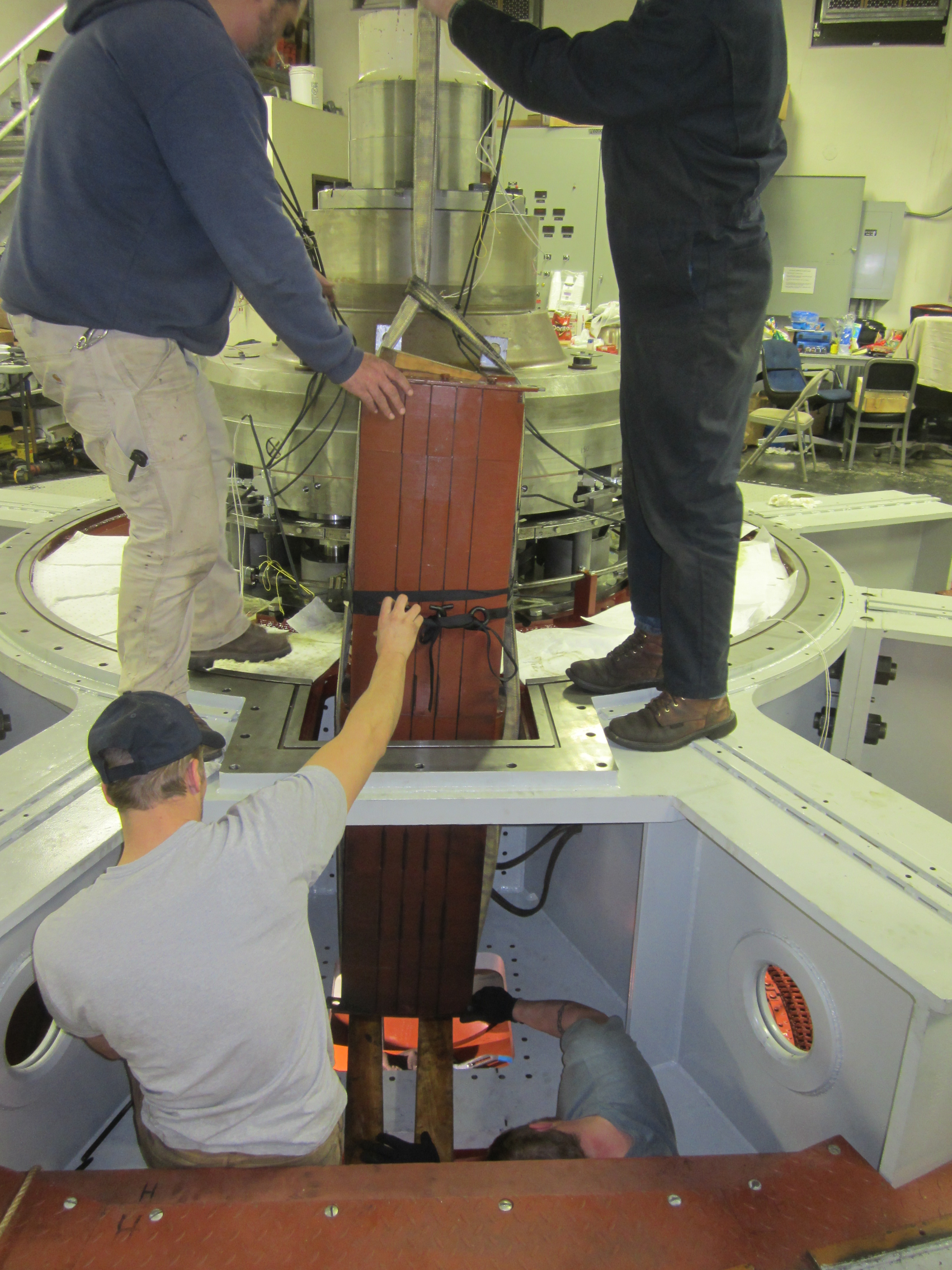
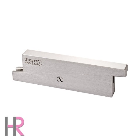
IV) Electrosila Pole Installation: As part of the procedure, for the radial bearing installation, the air gaps (the radial clearance), between the outer circumferential surface of the rotor and the inner circumferential surface of the stator, at the top of, and the bottom of, the rotor/stator were checked at each of the 22 poles with a set of Starrett precision parallels. The parallels were inserted in the gap, adjusted and pulled out. A Starrett outside micrometer was adjusted across the parallel surface of the parallels. The dimension was recorded.
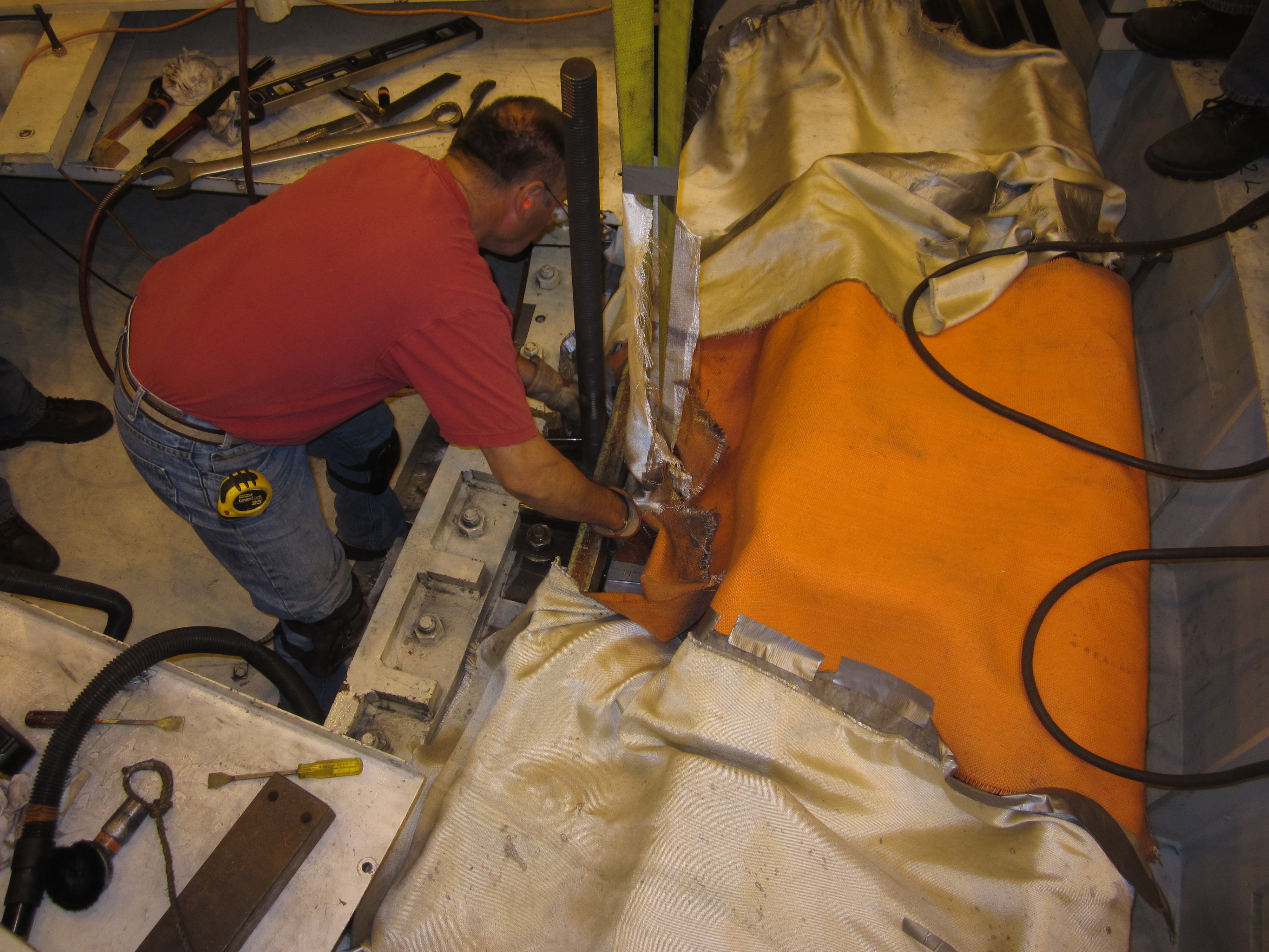
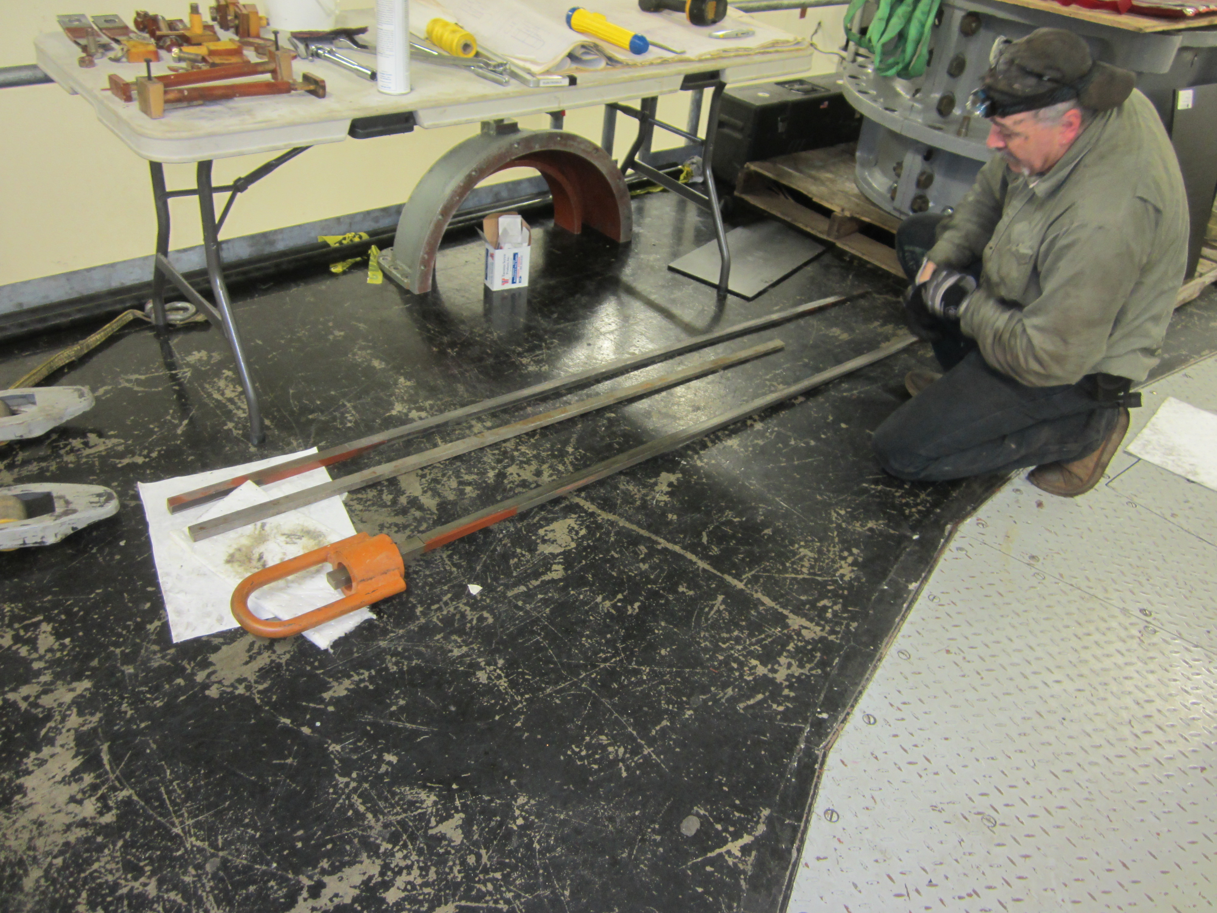
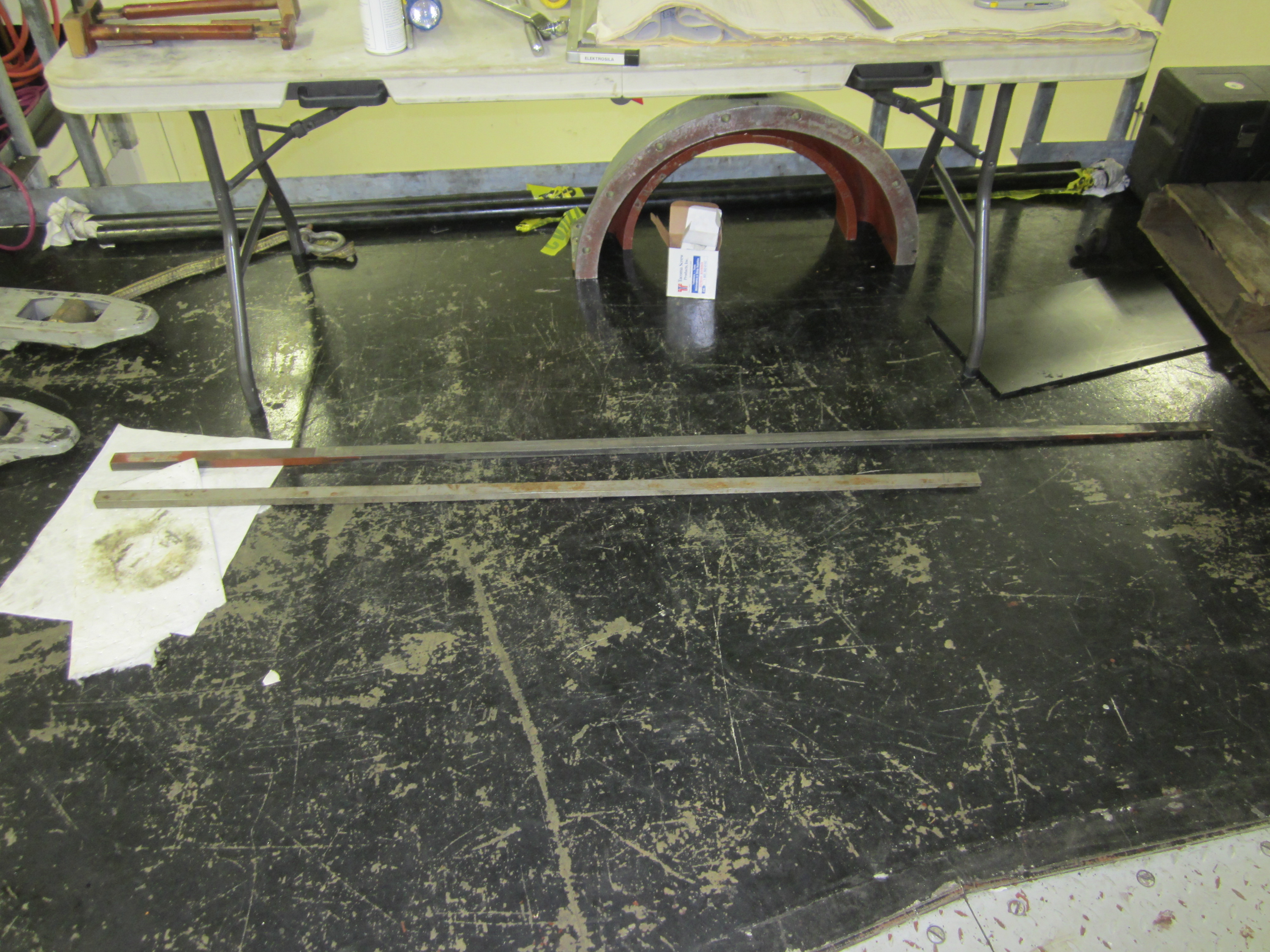
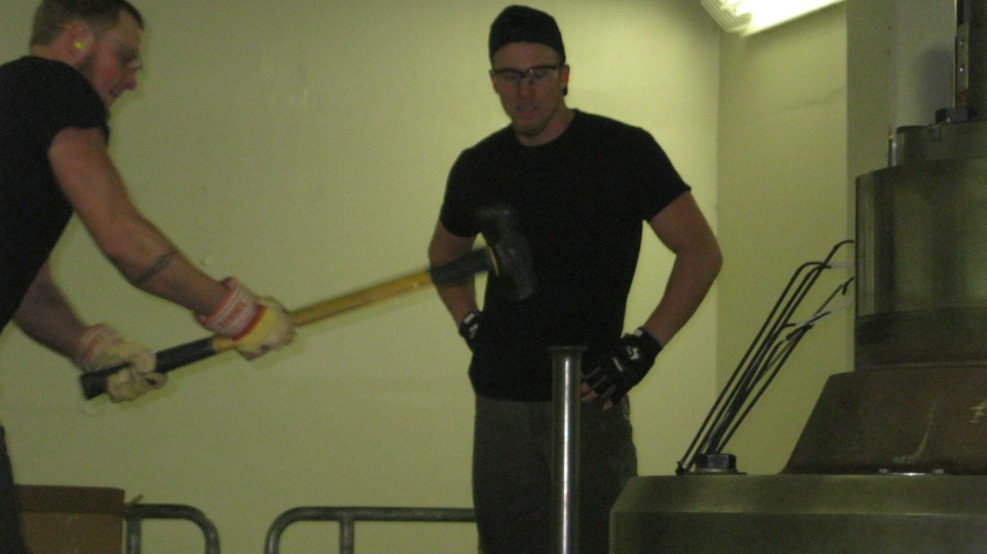
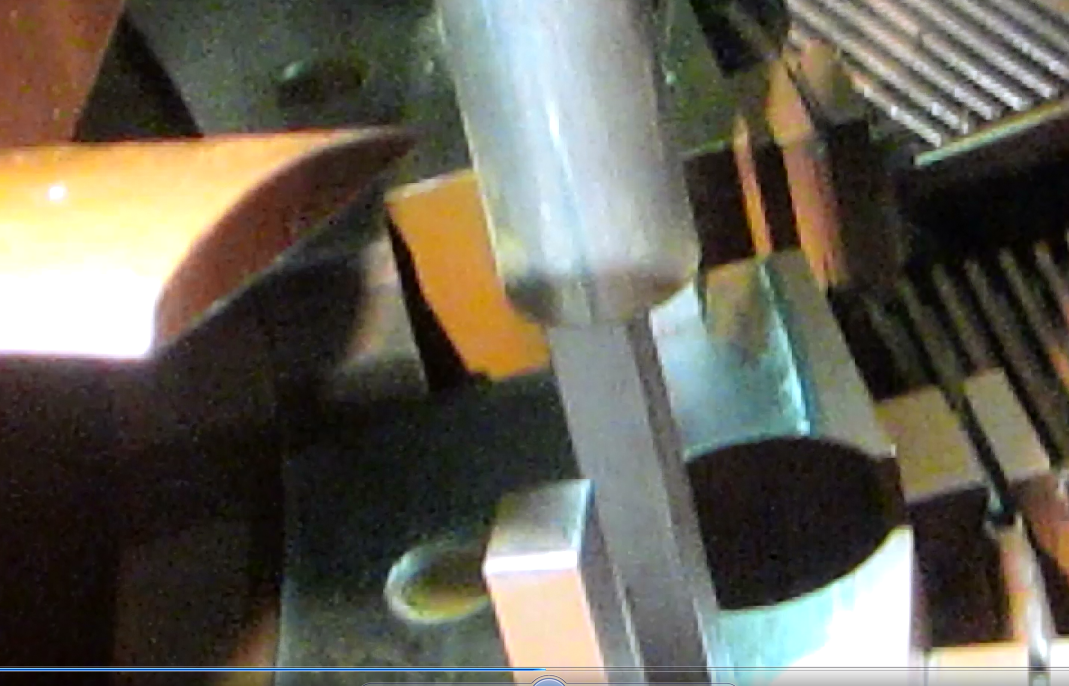
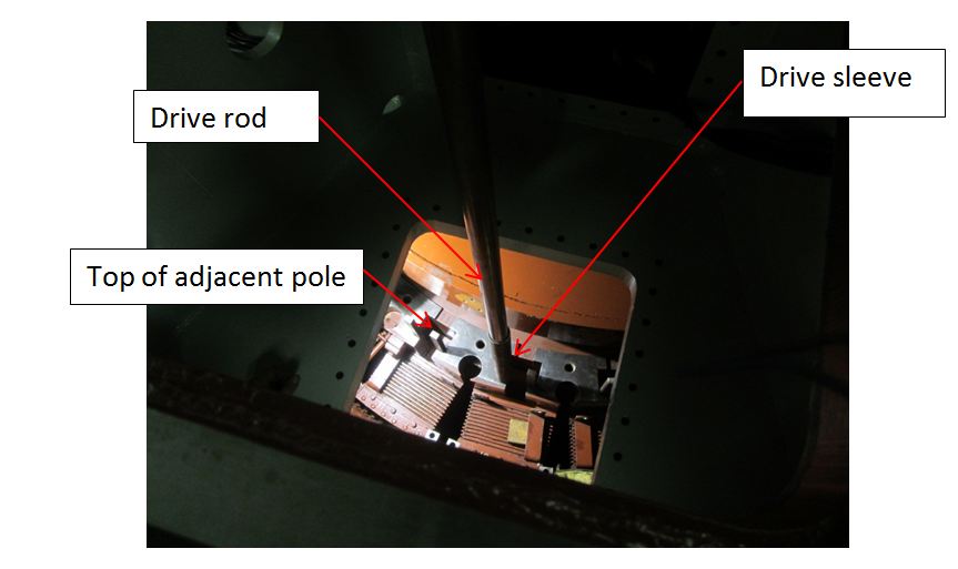
Precision Parallel, Note the adjusting screw used to slide the parallel wedges apart until they contact an upper and lower surface. A cursory inspection of the air gaps was disturbing. The air gaps at both the upper and lower locations were significantly different. More disturbing was the large average deviation between the two, upper and lower, sets of readings. The lower set, of air gaps, were significantly smaller than the upper set of gaps. The only reasonable conclusion was the twin sets of opposing wedges, forming the pole piece key securing system, were loose. The bottom of the keys was observed. They could be accessed by looking behind the brake ring. Using a tap hammer, 18 of the 22 poles could be easily moved sideways. The poles were loose. The worst set, of measurements, were observed on pole number 10. A discussion with the generator team resulted in the removal and inspection of pole number 10. To this end, the pole serial, bus, mechanical connections and outer bus support structures were removed at the top and bottom ends of the pole. These bus connections electrically connected pole 10 to the poles on either side of pole 10. A trip to the dead storage facility located the original pole extraction device. As described in a previous report, the pole was extracted and inspected. A debate arose regarding why the pole keys had loosened up. A close inspection of the rotor tee slot revealed the upper length of the tee slot was a different color from the bottom of the tee slot. It is unusual to place a Kaplan turbine at heads over 50 feet. This is due to the excessive run-a-way speeds of a Kaplan runner. A typical Francis runner, utilizing the reaction of the water pressure against its thin, uniform runner blades, will run away to 190 %, or almost twice, of its synchronous speed. A Kaplan runner, due to its design utilization of hydrodynamic lift on the airfoil shaped runner blades can exceed 3.5 to 4.0 times its synchronous speed during run-a-way conditions with a flat blade angle. During the transition from synchronous speed to a full run-a-way speed the rate of acceleration can be dramatically reduced by the addition of mass. This does not limit the maximum run-a-way speed. It does slow down how long it takes to reach full run-a-way speed. This delay allows the governor time to close the wicket gates safely and at the same time dump open the blades. The Russians knew this. They added a considerable mass to the unit in two ways. They made the rotor solid. They also added an enormous cylindrical weight. This weight was the same outside diameter as the periphery of the generator rotor. The two components were shipped separately on the freighter from Leningrad. Once the pieces were at the Wynoochee construction site, the separate, solid steel cylinder was heated up, slipped onto the generator shaft and allowed to cool down. This procedure created a heavy, force fit of the cylindrical mass to the generator shaft. The outer edge of the rotor and the added mass had corresponding tee slots machined in their outer surfaces. These slots were provided as mechanical attachment points for the salient poles. Unfortunately, the Russian machinists cut the tee slots to two different dimensions. The radial distance from the center line of the generator shaft to the bottom of the tee slot were different radii for the cylindrical weight and the rotor. The radius of the bottom section, of the rotor was smaller than the top half of the tee slot. This left a 0.008 inch discontinuity at the back of the tee slot between the upper and lower pieces of the rotor. When the keys were driven in, they expanded, filled up the upper half of the slot and secured the upper half of the pole to the rotor. Unfortunately, the discontinuity prevented contact between the rotor, the keys and the pole on the lower half of the tee slot. This left the lower halves of the pole pieces cantilevered off of the top of the rotor with no support. The lack of lower pole support creates a horizontal shear plane at the point of discontinuity. With this condition, there is a real possibility of interstitial movement between the pole laminations. When this happens the pole becomes distorted along its vertical axis. This condition was checked by the use of an eight foot carpenter's level as a straight edge. The level was placed against the back of the # 10 pole. A feeler gauge set was used to try to insert a very thin feeler gauge between the level and the pole. An 0.008 gauge could be slid beneath the level at the midspan of the pole piece. As it was moved towards the two ends of the pole it became tight. This indicates a very slight bow in the length of pole #10. The bow could be the result of bad construction techniques or it could be from being unsupported for half of its length. A hearty discussion ensued regarding how to move forward. We could re-drive the existing keys or replace the existing keys. In order to assist us in the decision making process, HCMS brought in their generator expert, Mr. Earl White. Mr. White was asked to inspect the #10 rotor pole, the rotor pole slots and the pole keys. As a result of the inspection, Mr. White proposed a redesign of the pole wedges that would resolve the tee slot alignment issue. At the time, Tacoma's intention was to pull all the poles, clean them and re-install them utilizing the wedge system proposed by Mr. White. Mr. White did a comprehensive redesign including calculations and drawings. The White key system has the advantage of compensating for the differences in tee slot, bottom radii, between the top and bottom sections, of the rotor. Depending upon its price, it could be very cost effective, when compared to removing the rotor, laying it on its side and having the base of each of the 22 tee slots, insitu milled, to a common radius. The drawings were going to be forwarded to A F Dick Machine, for an estimate of the cost and delivery schedule for the replacement keys. As a result of the ongoing unknowns, as to cost and delivery of the key system, rising project costs in general and extensions to the completion date, (in no way HCMS’ fault), Tacoma decided to not replace the pole keys, at this time, and redirected HCMS’ efforts to re-driving the existing poles. Originally, the pole keys were installed with the rotor on cribbing setting outside of the stator. This exposed location allowed a hefty and complete swing with a sledge hammer. Unfortunately, the rotor is installed in the stator and the keys are located beneath the upper bracket. There exists a minimal space to swing a hammer though an abbreviated arc. In order to overcome this limitation, on hammer swing, a pole key driving system needed to be created. Bryan Steurmann, of Port Machine, Mike McCoy of Cushman, Regan Lee of HCMS and Bill Fay discussed several options. The best solution was presented to Bryan to fabricate the components. The system consisted of a piece of a 9 foot long, 2 inch diameter, polished steel shaft, used as the drive rod, an 18 inch long piece of 2 1/2 inch, schedule 40 pipe, used as the drive sleeve and a 16 pound sledge, used to strike the top of the drive rod. The ends of the drive rod and dry sleeve were carefully ground to remove all burrs. The inside of the drive sleeve was cleaned and blown dry. The 9 foot drive rod was lowered down through the two rectangular pole removal hatches, provided in the floor and ceiling of the upper bracket, until it rested on the head of one of the sets of keys. The drive sleeve was placed over the top of the drive rod and slipped down the drive rod until it encompassed both the lower end of the drive rod and the top of the pole key. The drive sleeve is used to contain the drive rod on the head of the pole key during the driving process. When the sledge hammer impacts the top of the drive rod the bottom of the drive rod recoils upwards. If the drive sleeve was absent, the drive rod could slip off the top of the pole key and damage the rotor and/or stator windings. Even with the pole key driving system, it took three men to drive the keys. The top man swung the sledge hammer, another man held the drive rod while standing below the ceiling of the upper bracket and the third man was at the drive sleeve making sure the drive rod stayed in the drive sleeve. He also held the drive sleeve up while the drive rod was moved to the second key set. Initially, the top man jerked the drive rod up and down. This action simulated an inverse slide hammer to drive the key down. After reseating the key by this method, the 16 pound sledge was used to drive the keys further down the tee slot. The crew noticed that after driving both sets of keys to a hard ring, they went back and checked the first set of keys. To their surprise, the set of keys first driven were still slightly loose. They modified their drive procedure to go back and forth between the two sets of keys until they rang true. It was postulated that an additional cause of the loose pole keys, besides the cantilevering of the lower half of the pole in the tee slot caused by the discontinuity in the slot, may have been the original pole key installers drove one set of keys to a solid ring. They switched sides to the second set of keys and drove them to a tight ring. They thought the pole keys were tight and never checked to find that the first set had loosened up during the process of tightening the second set of keys.
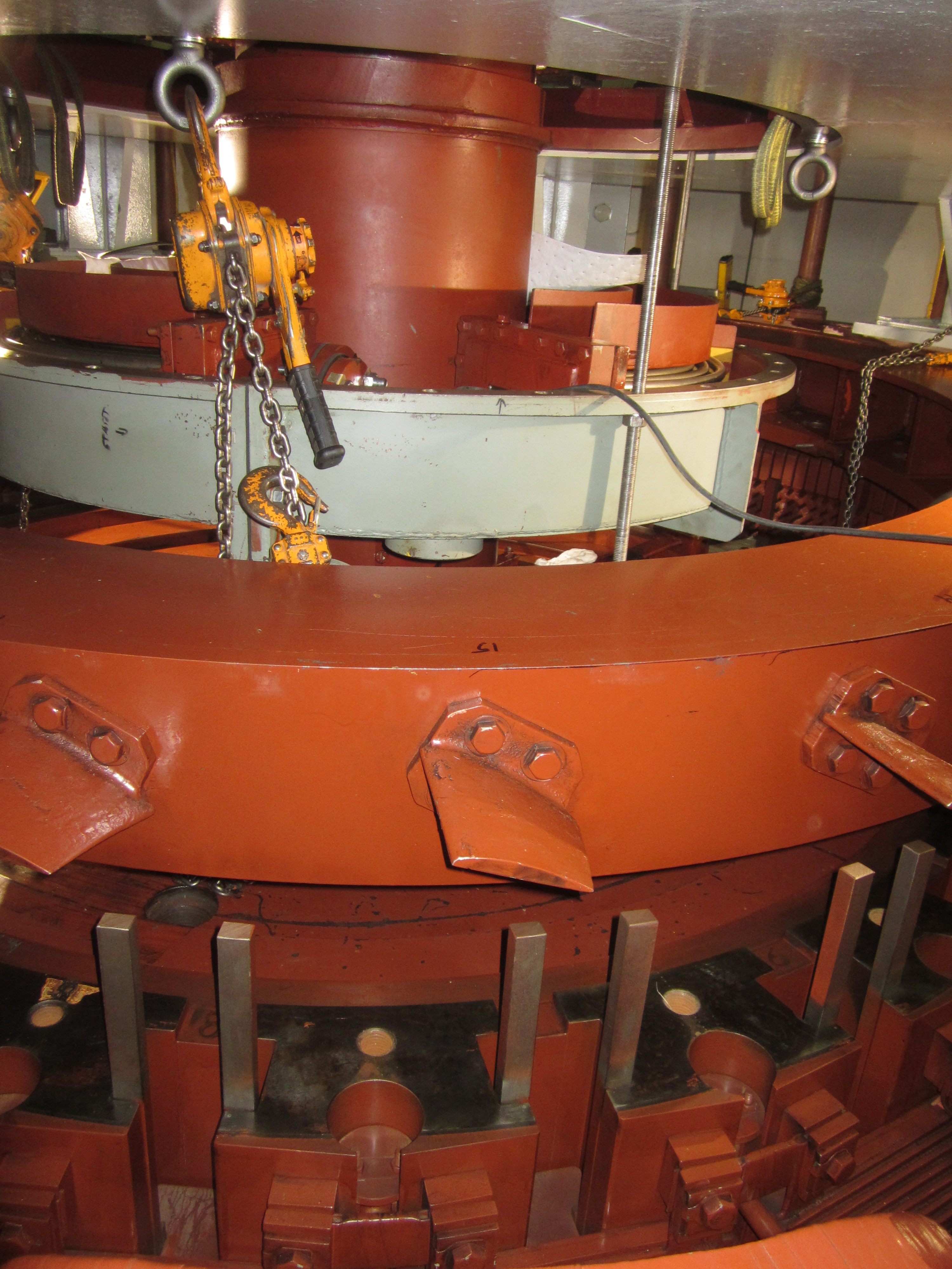
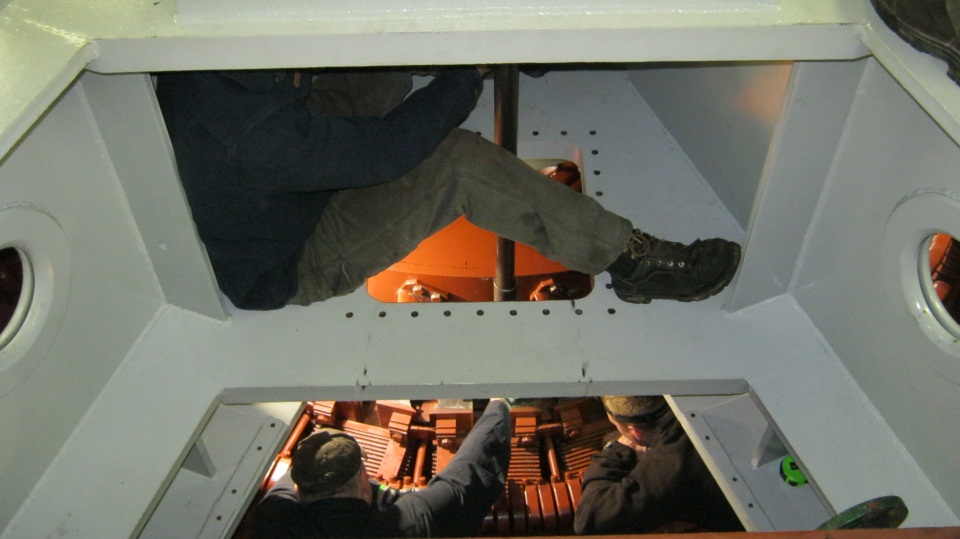
Figure 1: Inserting the 9 foot drive rod down through the two rectangular pole piece extraction hatches.
Figure 2: Inserting the 9 foot drive rod down through the two rectangular pole piece extraction hatches.
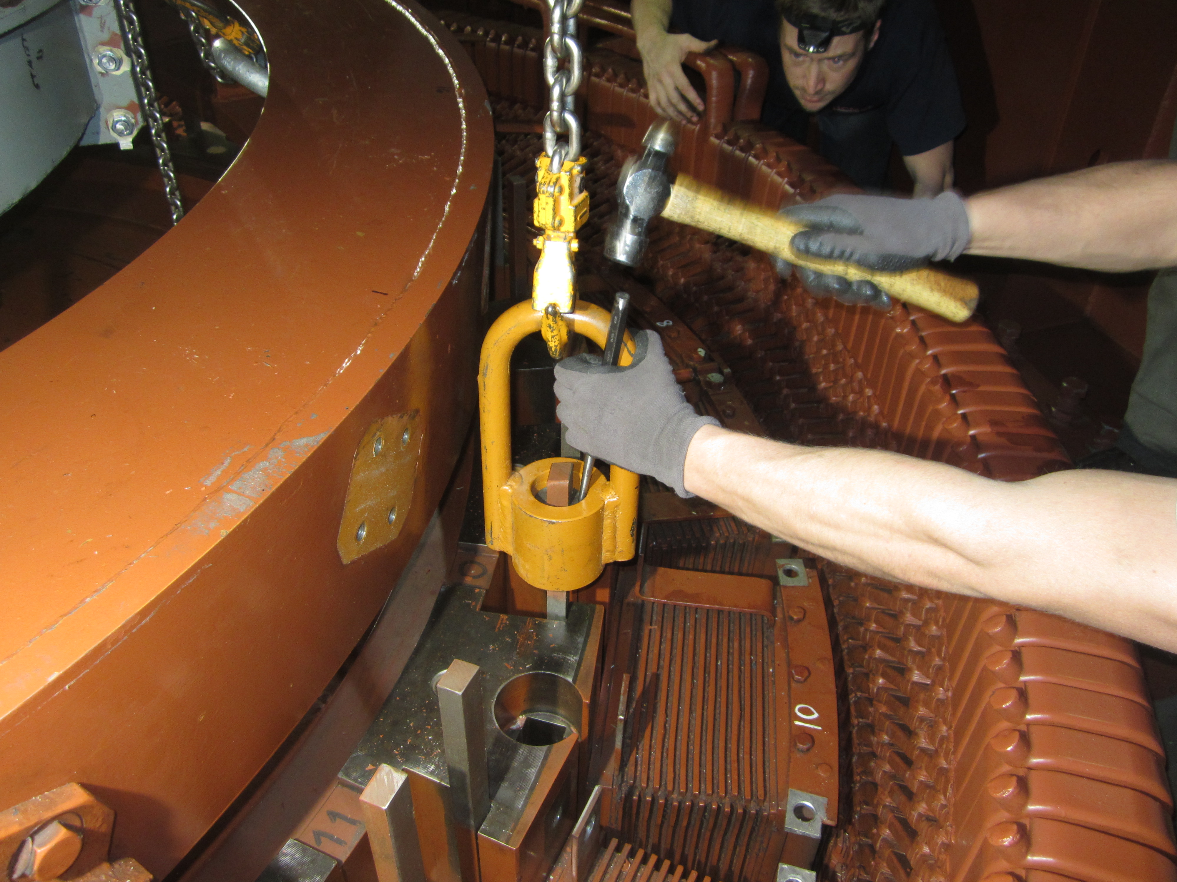
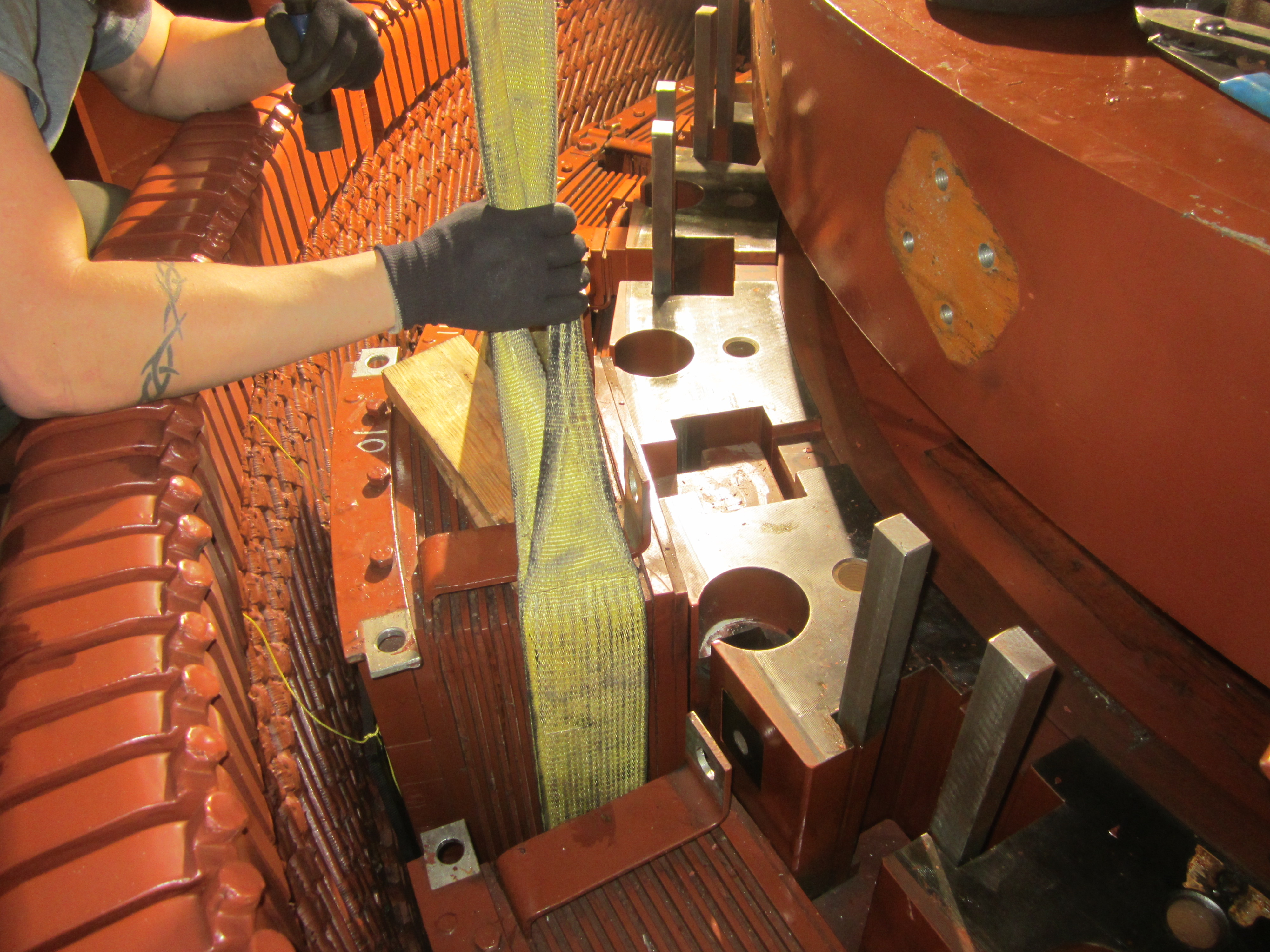
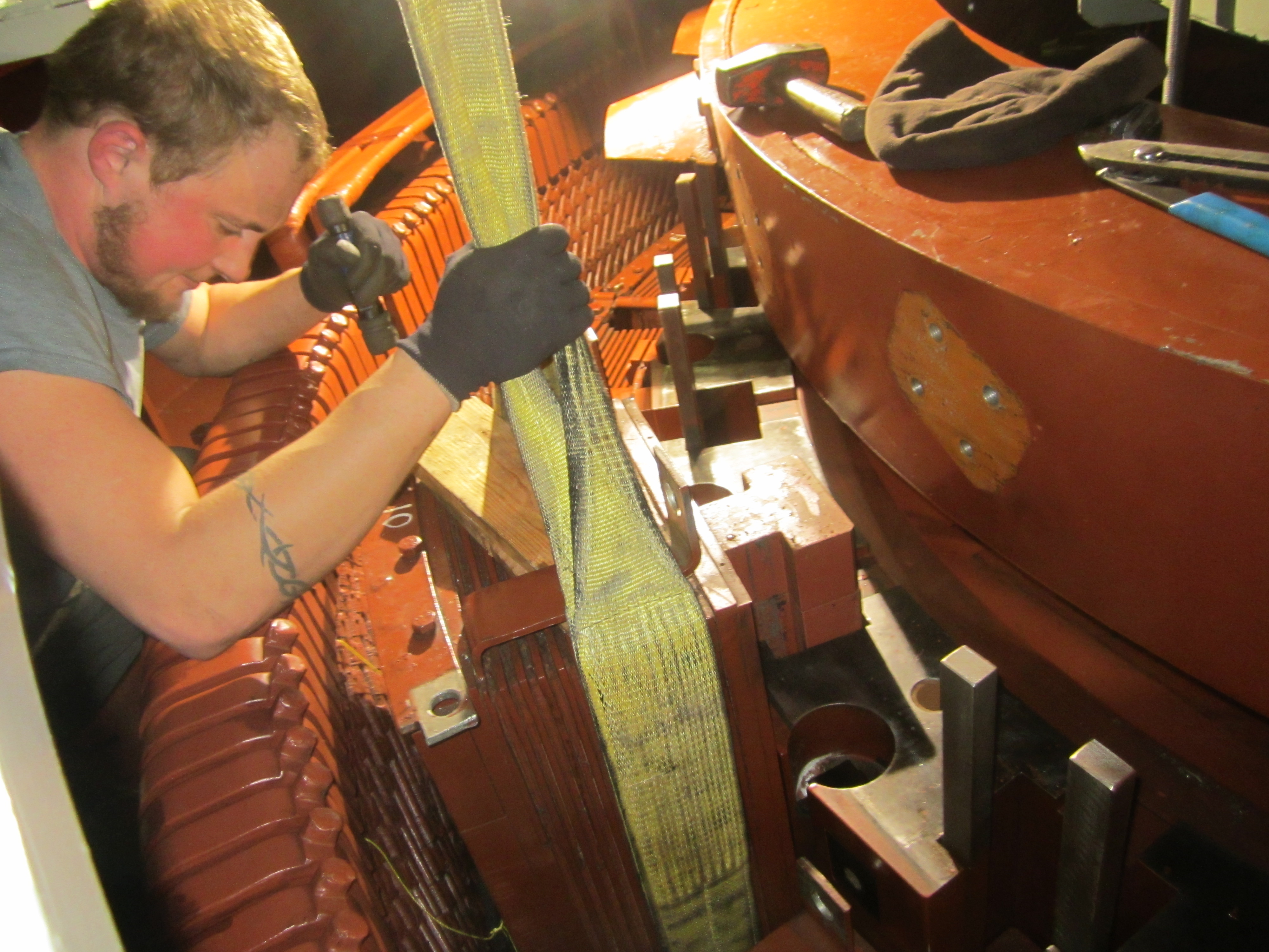
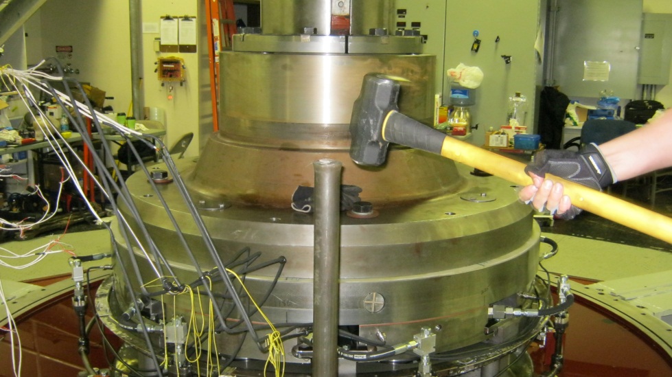
Figure 3: A 16 pound sledge hammer used to drive the 9 foot drive rod down onto the top of the pole key.
Figure 4: Jed using a 16 pound sledge hammer to drive the 9 foot drive rod down onto the top of the pole key.
Figure 5: Colton takes over using a 16 pound sledge hammer to drive the 9 foot drive rod down onto the top of the pole key.
Figure 6: Note the head of the drive rod starting to mushroom.
Figure 7: One man supports the middle of the drive rod while the bottom men measure the key insertion progress.
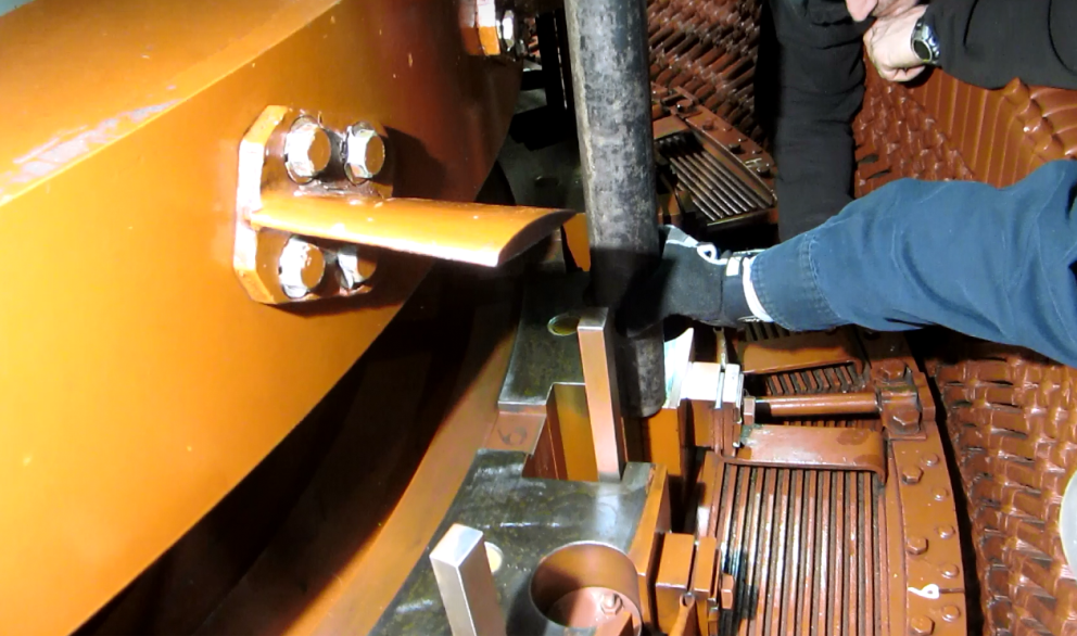
Figure 8: A view of the drive sleeve that prevents the drive rod from bouncing off the pole key.
Figure 9: The drive sleeve being lowered over the pole key.
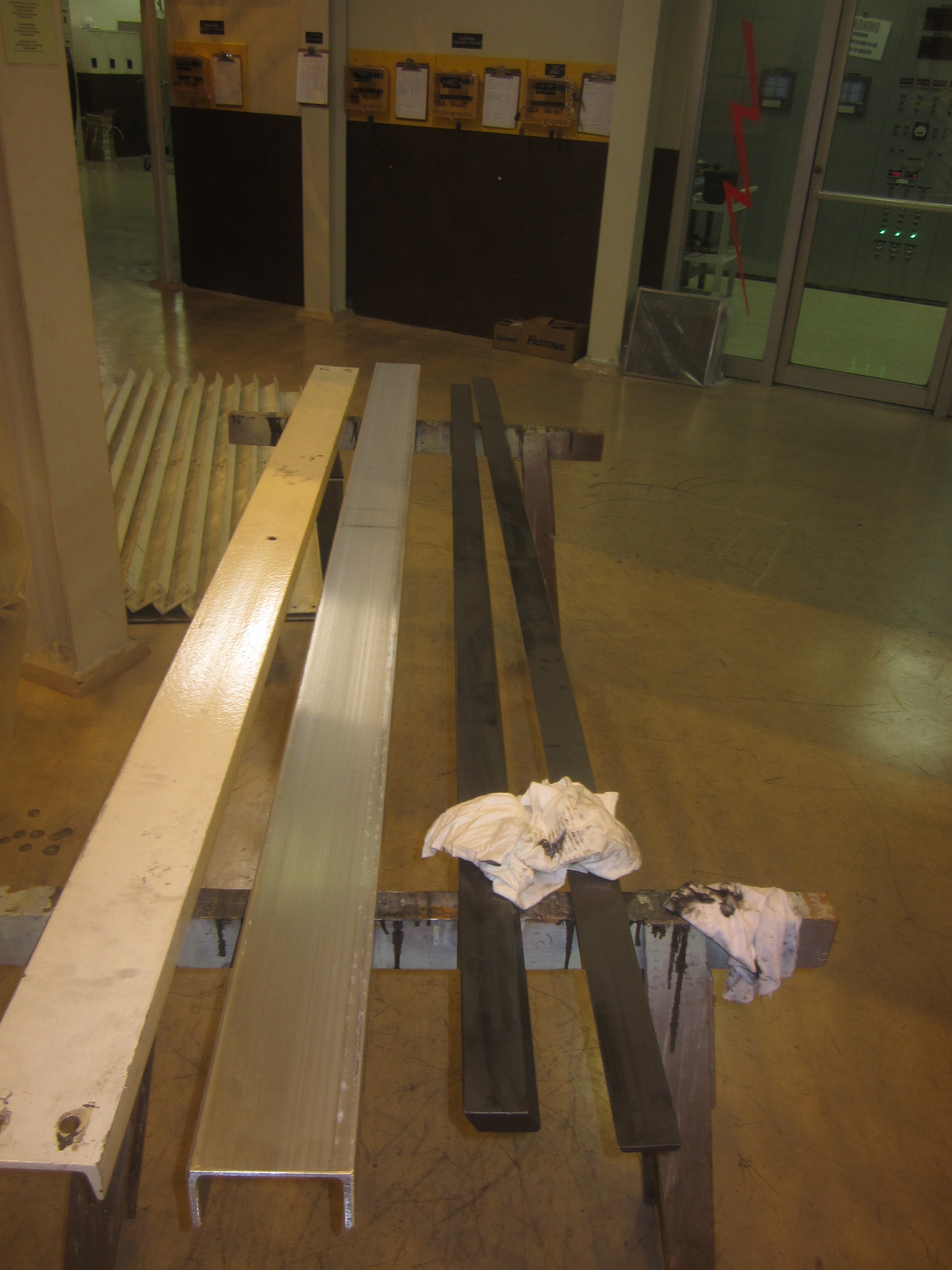
IV) Tools of the Trade:
Figure: Side view of pole storage frame.
Figure: Frontal view of pole storage frame.
Figure: Pole extraction device.
Figure: Pole extraction device in use.
Figure: Pole rigging device.
Figure: Installation of pole rigging device.
Figure: Frontal view of coil separation tongs. These tongs are used to lift the copper coil from the steel laminated armature.
Figure: Side view of coil separation tongs. These tongs are used to lift the copper coil from the steel laminated armature.
Figure: Coil removal tongs used to dismantle copper coil from armature body.
Figure: Trim control lifting clamp for attaching to pole tee.
Figure: Wedge driving chisel with shock absorbing wire rope handle. This is for double jacking the narrow end of a pole key's wedge.
Figure: Wedge driving chisel with shock absorbing wire rope handle. Note the chisel end has been ground to match the end profile of the small end of a wedge.
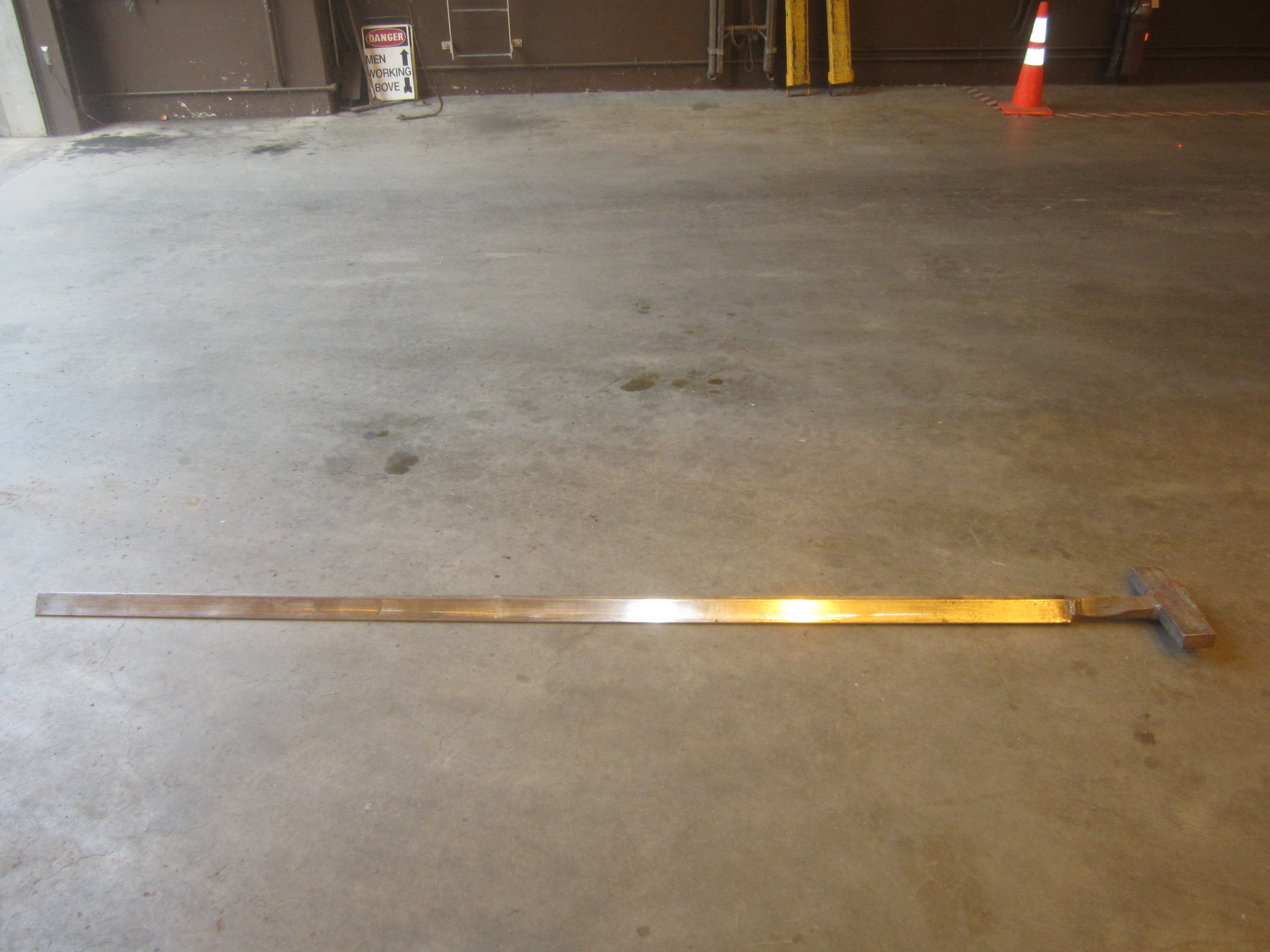
Figure: Tee puller welded to the end of a pole key. A lifting strap is attached to the cross bar and the pole is extracted with the bridge crane.
Figure: Driving mandrel for use in a 80 pound pavement breaker.
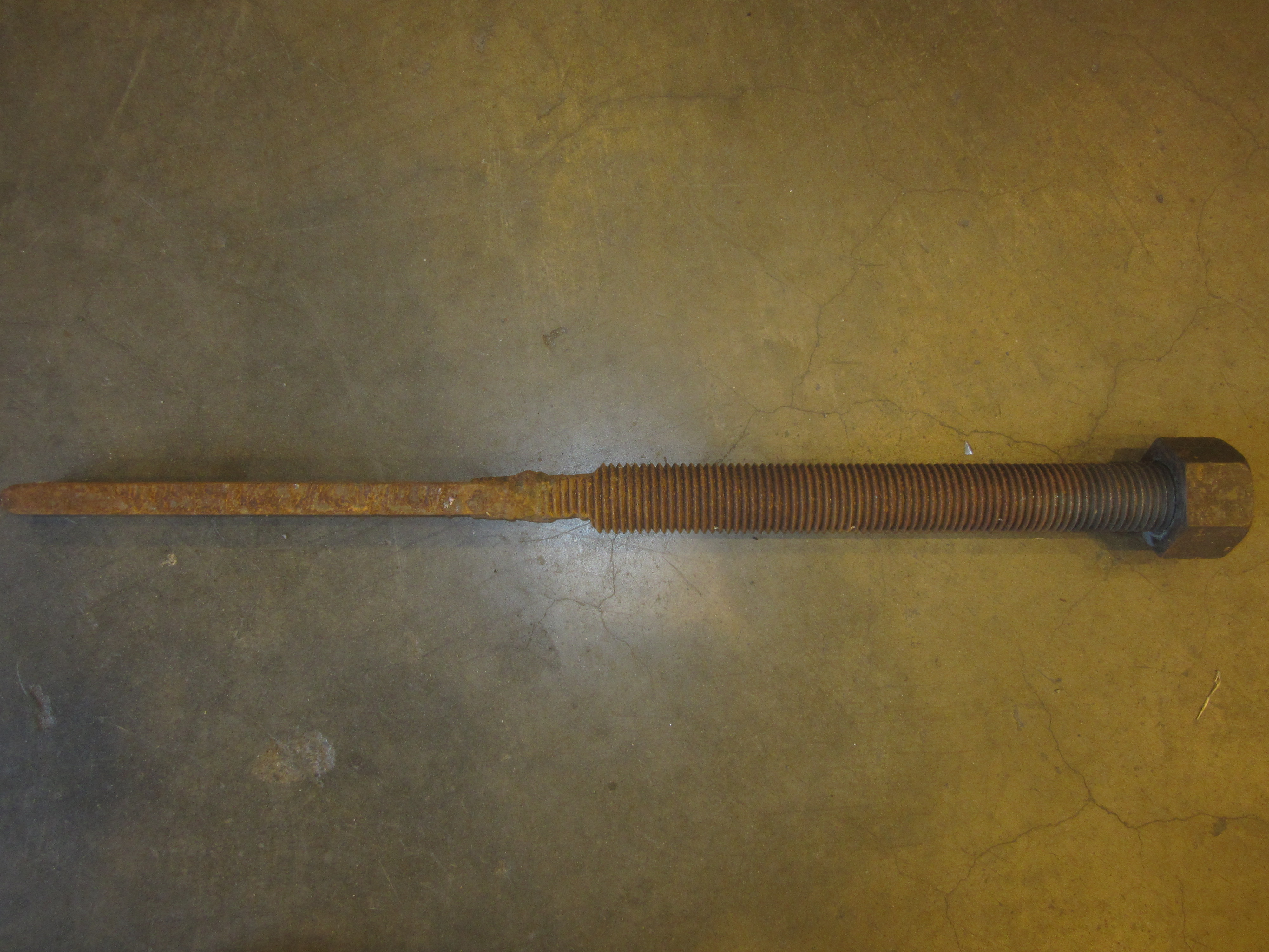
Figure: 1 1/2 inch threaded rod. The end has been milled down to a rectangle the same dimensions as the large end of a pole key's wedge. It was then welded onto the pole key. A jacking column was dropped over it and a strong back was slid down the rod and seated across the jacking column. The nut was spun down the threaded rod and a slug wrench was used to pull up on the wedge to extract it.
Figure: Site forged slug wrench for turning the 1 1/2 inch nut.
Figure: Hollow core, dual acting, hydraulic ram. This is utilized with a longer threaded rod to extract the wedge. It is slid over the threaded rod that is welded to the end of the pole key wedge. A large washer and nut is spun down the threaded rod to secure it. It acts both as the jacking column and the means to apply the extraction force.
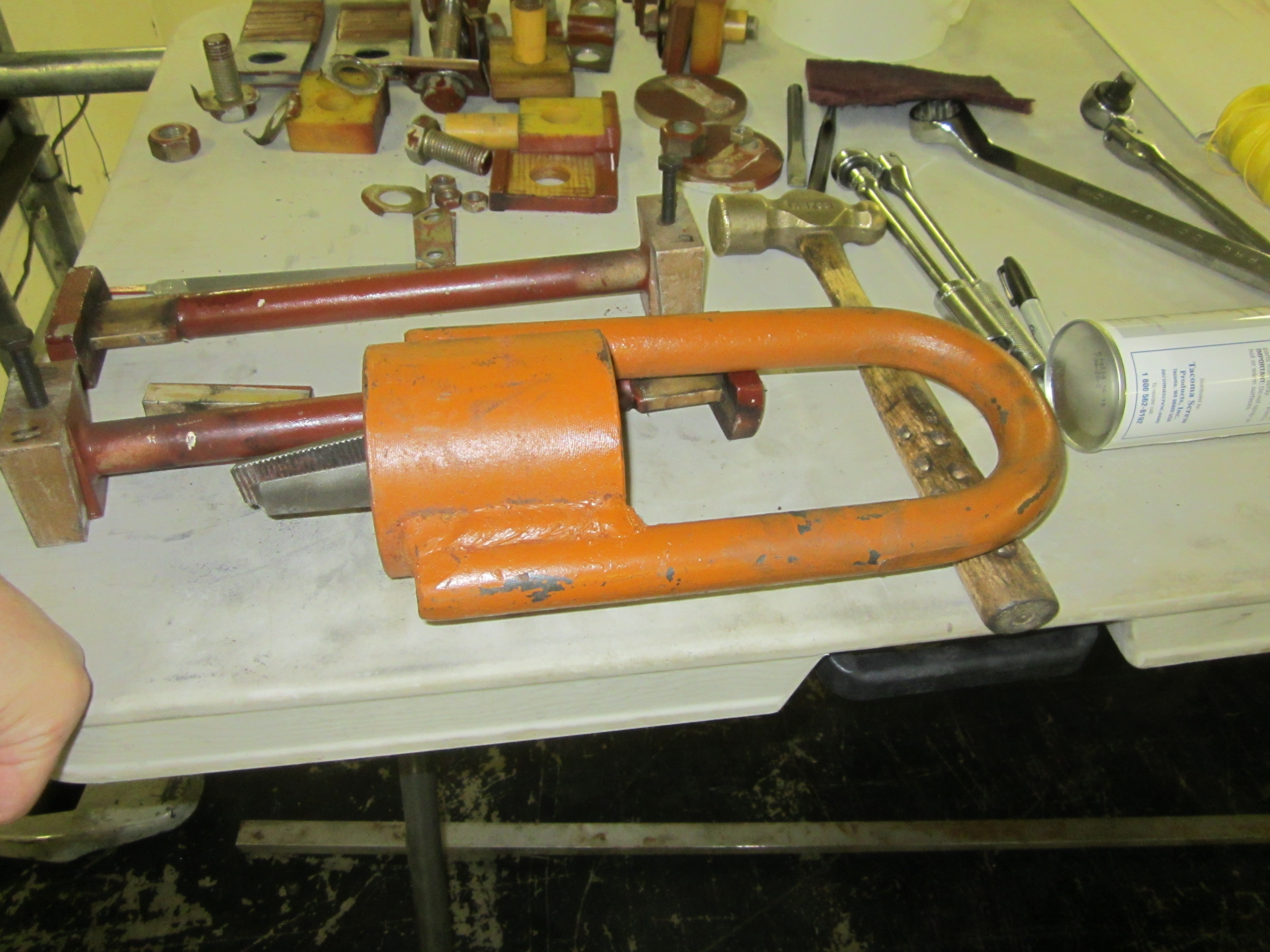
Electrosila contracting wedge jaw pole key extraction device.
Electrosila contracting wedge jaw pole key extraction device.
Electrosila contracting wedge jaw pole key extraction device.
Electrosila contracting wedge jaw pole key extraction device.
|
|
|