MACHINE SHOP PAGE
The machine shop is located in Wilbraham, MA. It was originally assembled to repair our own hydro plants. As word of our abilities spread, we have been doing outside jobs for utilities and other developers. The shop now includes a Niles, 120 inch vertical turret lathe, a Bullard, 60 inch vertical turret lathe, a Bullard, 24 inch vertical turret lathe, a Lucas, 4 inch horizontal boring machine, a Poreba, 33" by 28 feet engine lathe, a Cincinnati Bickford, 15 inch column radial arm drill, a 100 ton iron worker, a 100 ton press and numerous milling machines and smaller lathes.
The following photographs illustrate some of the machines doing typical hydroelectric repair work.
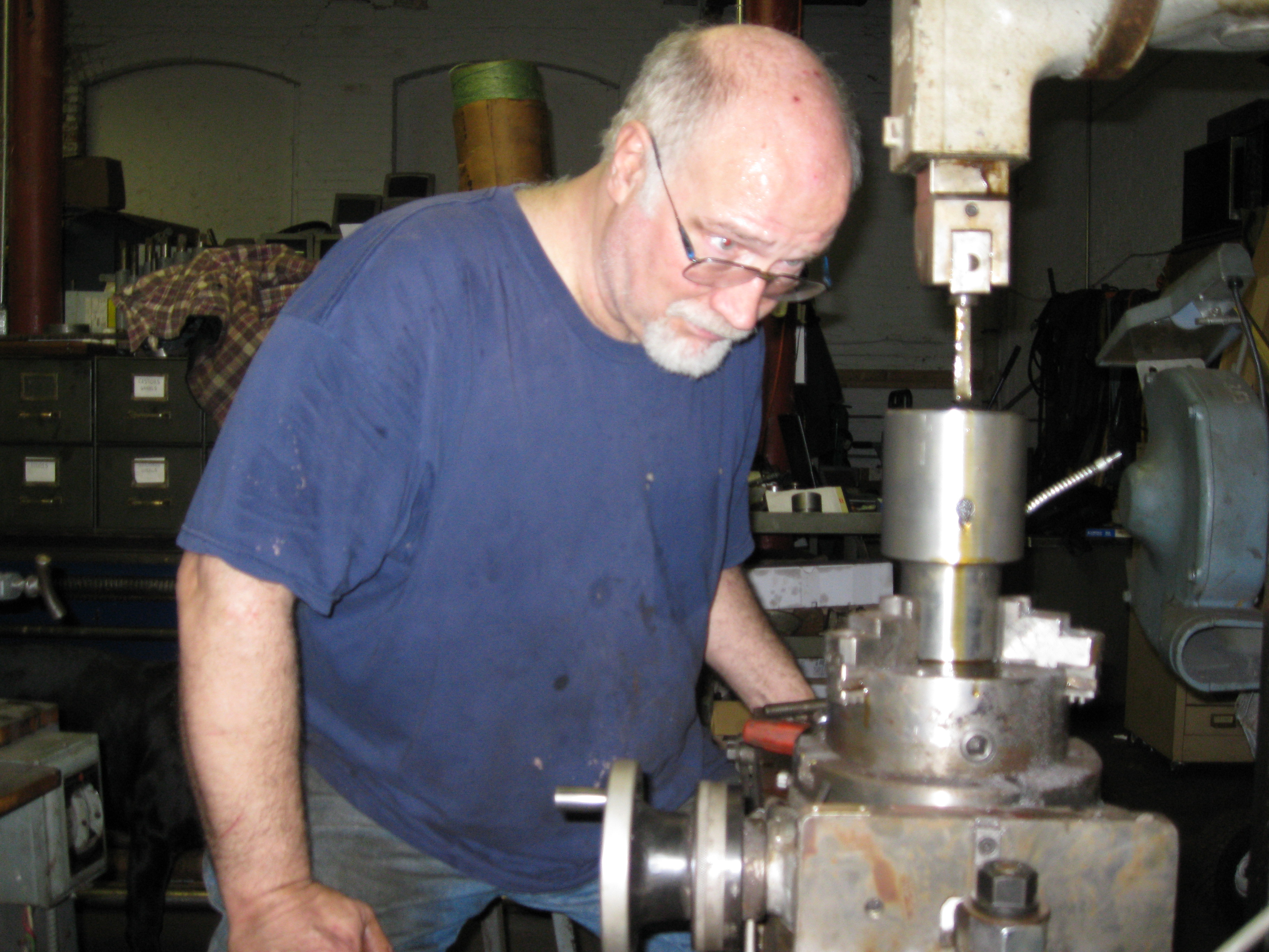
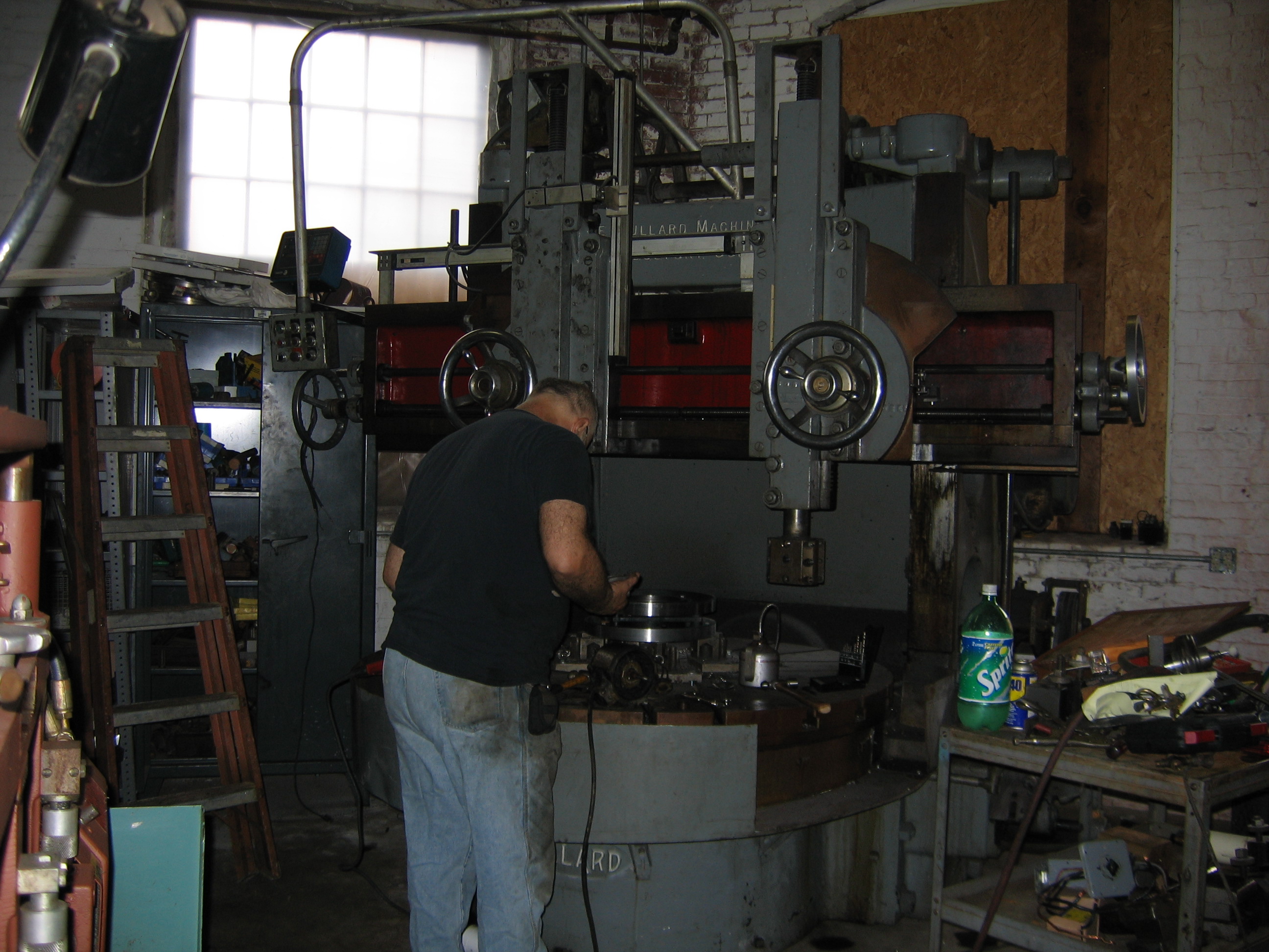
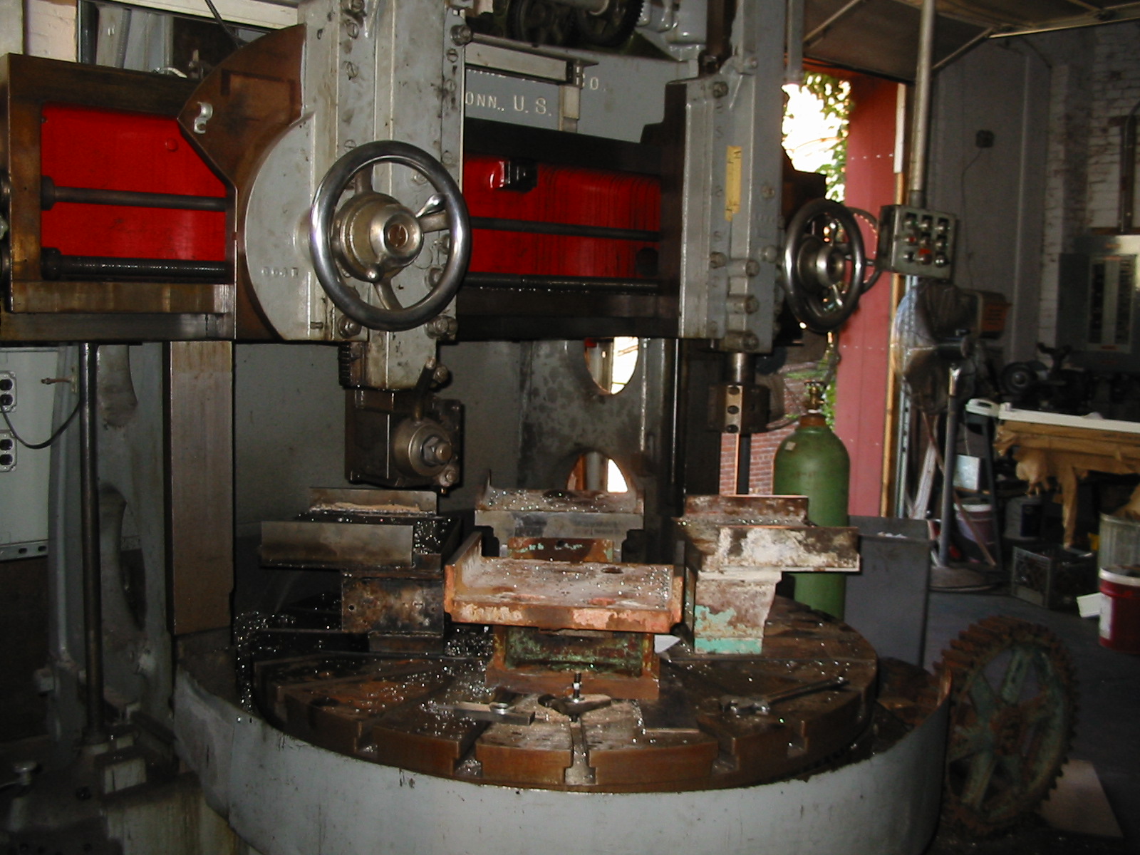
Here, The Wizard is machining the head cover/wicket gate case crown on the 120 inch Niles boring machine. We had to make riser blocks for the chuck jaws in order to hold the 2600 pound cover on the table. We are skimming the surface of the plate where the wicket gates swivel in order to remove 70 years of corrosion. This will re-create the sealing surface to restore our volumetric efficiency.
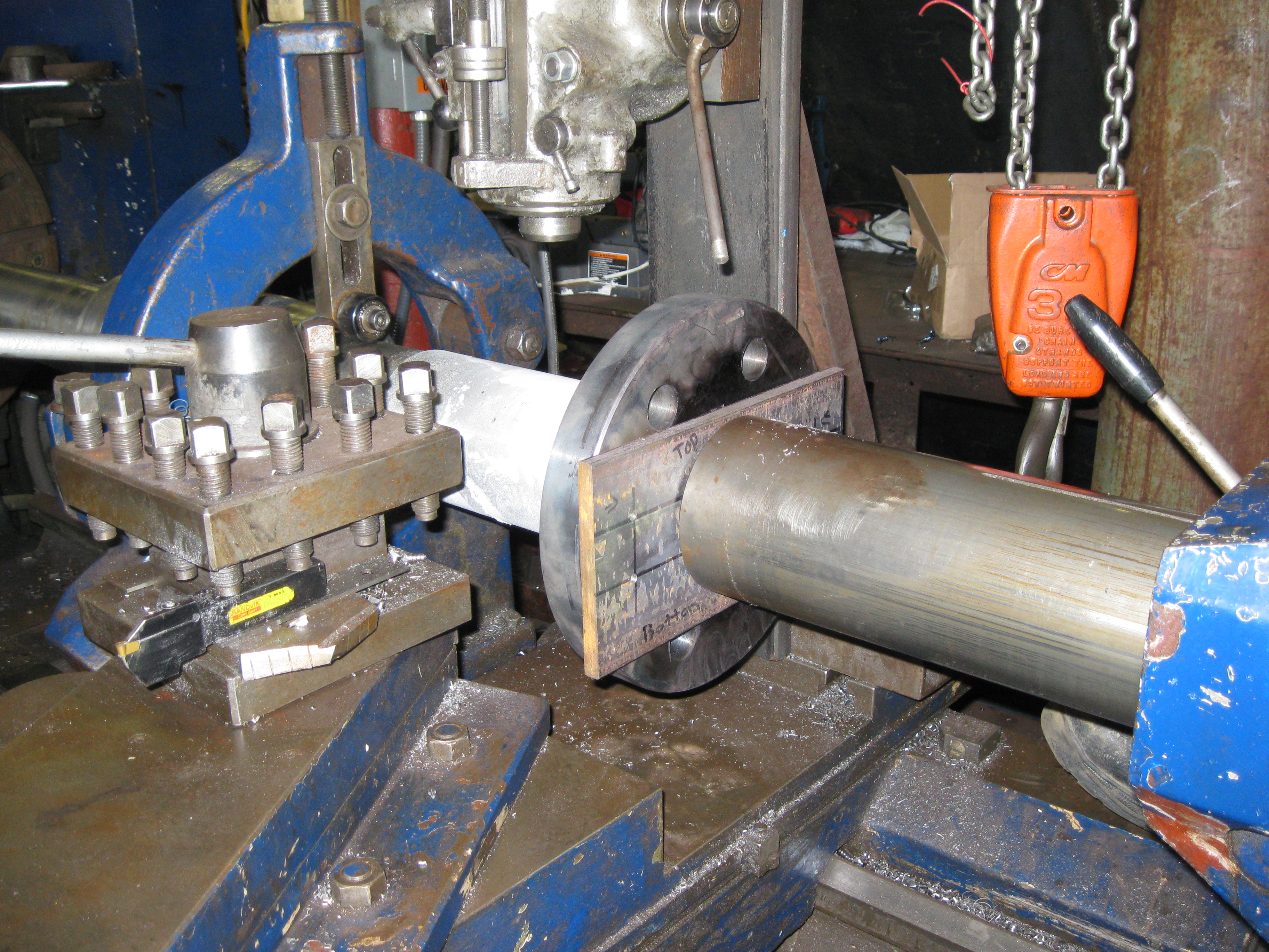
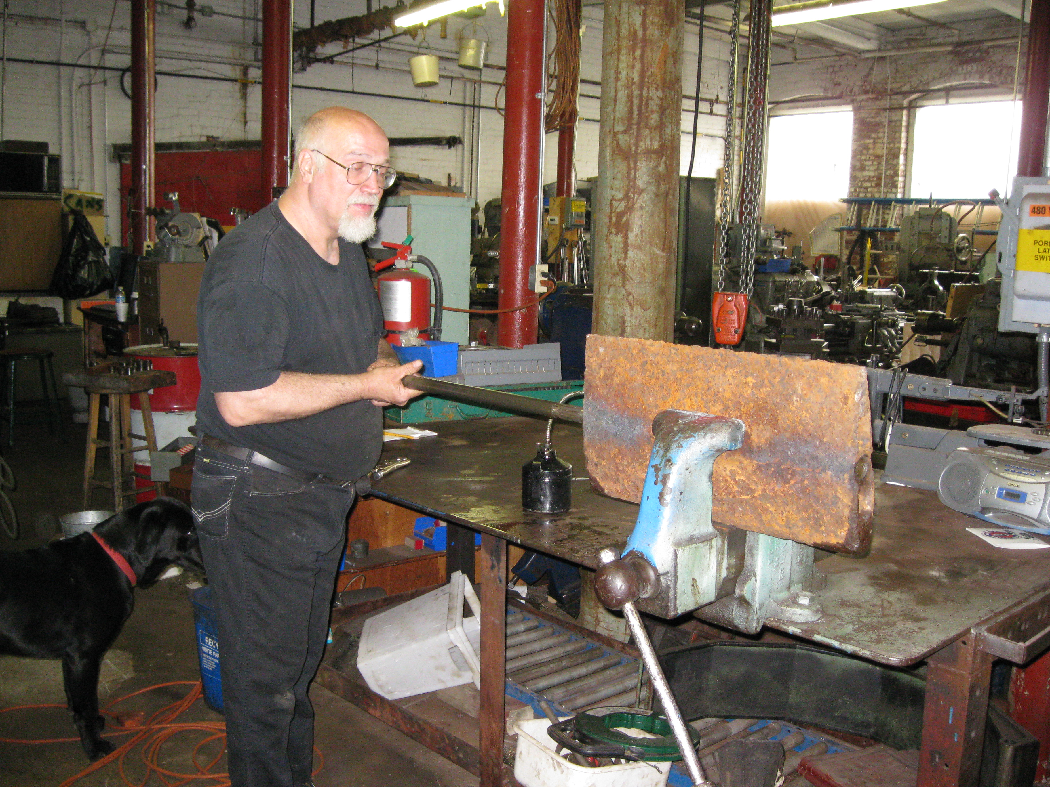
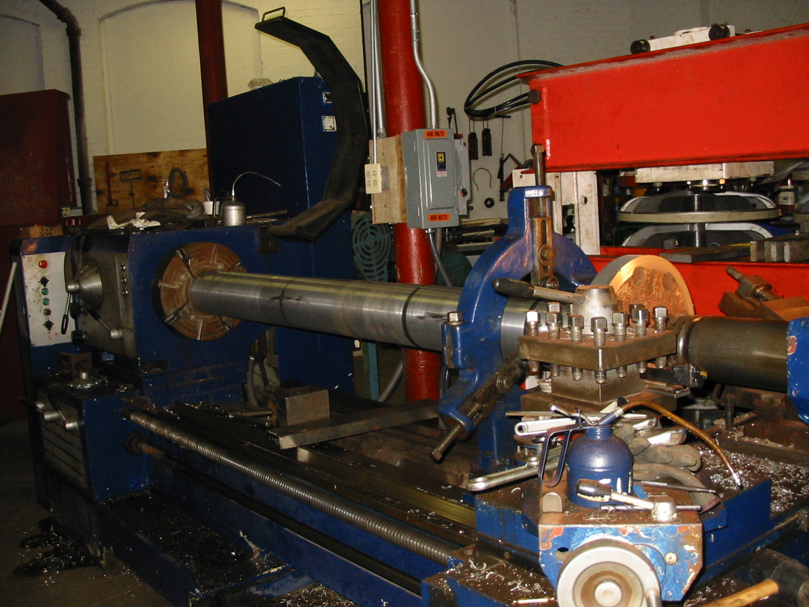
Here we are making a heavy, force fit of a coupling to a new thrust shaft. We have heated the shaft up in an old oven to 500 degrees F. We cooled the shaft with dry ice. You can see the heavy frost on the surface of the shaft. You can see how hot the coupling is. We used hot mittens to place the coupling onto the end of the shaft. We are using the tailstock ram of the big Poreba Roll Lathe to push the coupling onto the shaft.
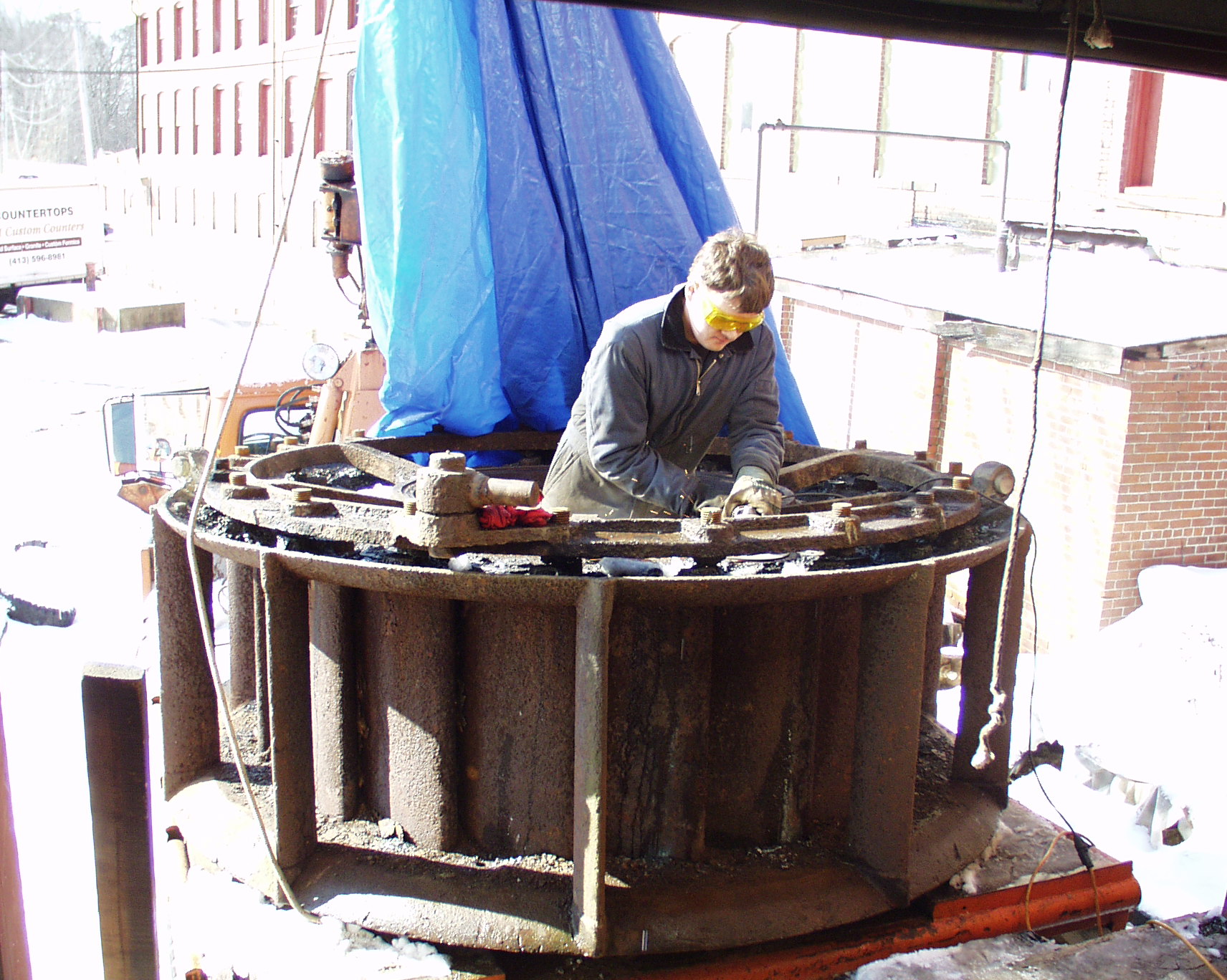
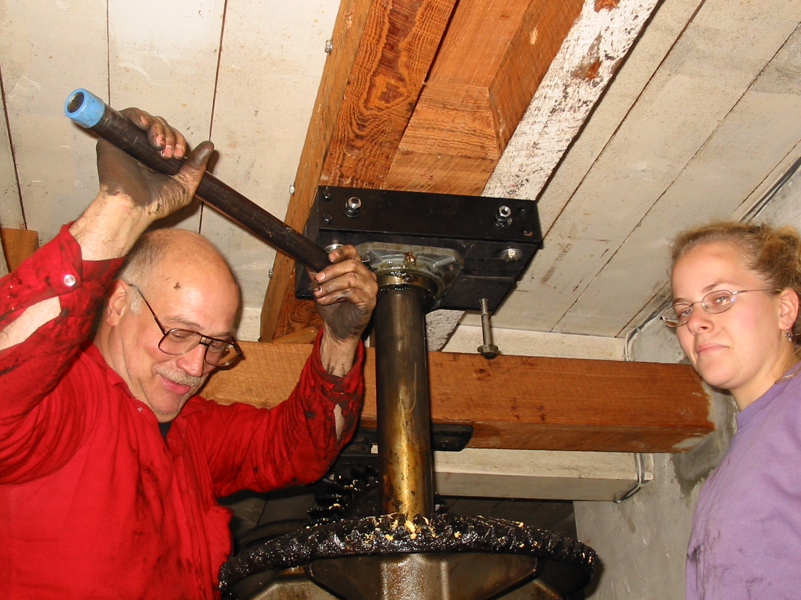
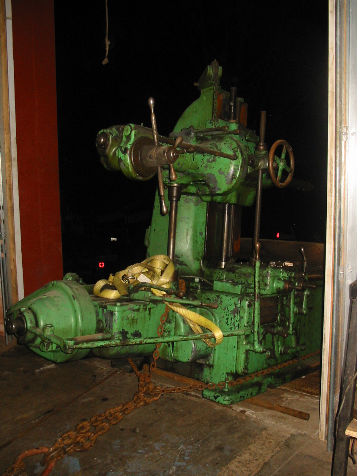
Here, we are dismantling a Leffel 39" Type "B2" Francis turbine that I had pulled from the Hudson river in 1992. This unit was completely rehabbed and is installed in our Pepperrel Hydro Plant.
The Wizard making a shaft coupling.
Here, we have made a large coupling and we are using a universal keyway cutter to machine the internal keyway.
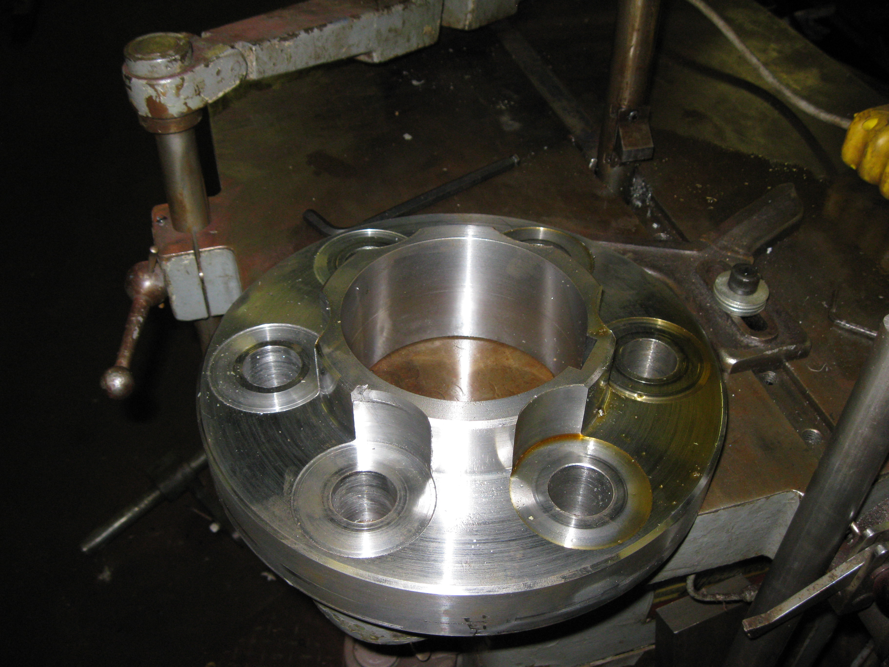
The Wizard fitting a new gate axle to an older wicket gate. We inserted new bronze bushings into the gate bore. We have reamed the bushings to size and we are checking the fit. Tut the supervisor dog is barking out orders in the background. Warren rarely listens to him!
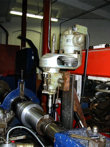
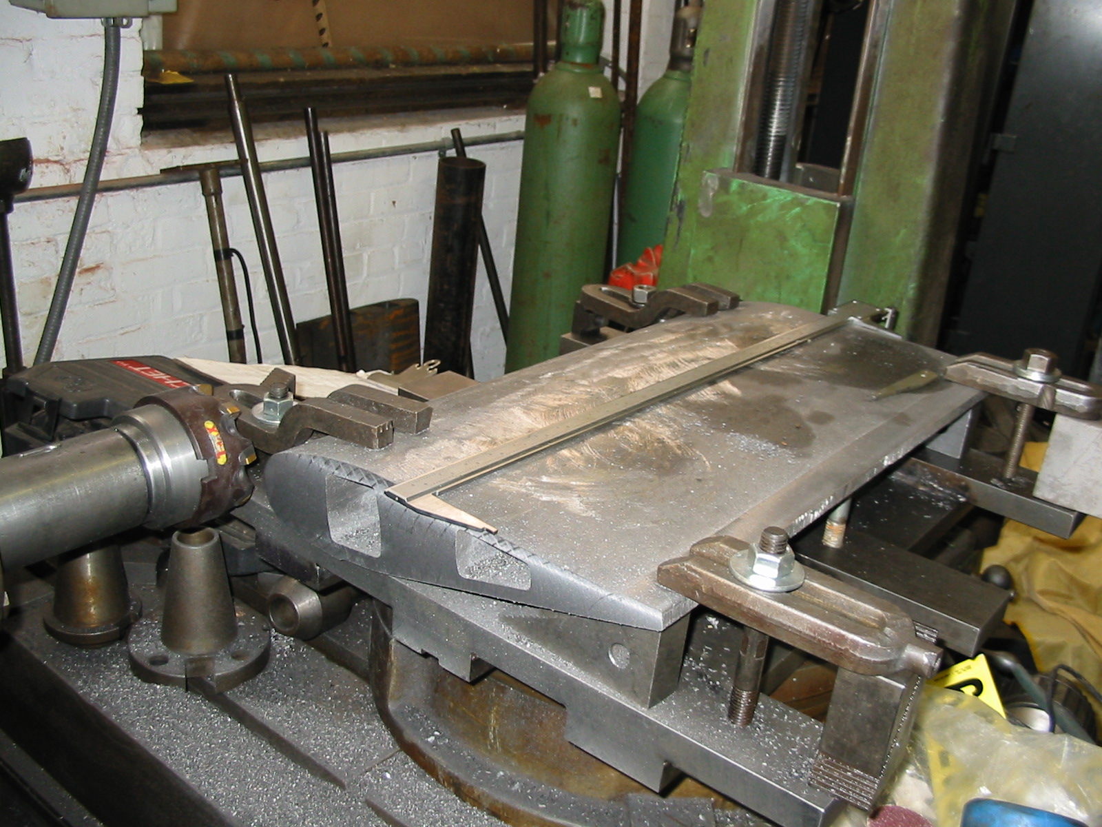
This Bridgeport head has been mounted on the cross slide of the Poreba Lathe to turn it into a milling lathe!!
Leffel stay vane being machined.
Leffel wicket gate being machined.
Upper bushing nuts being turned from hexagonal stock.
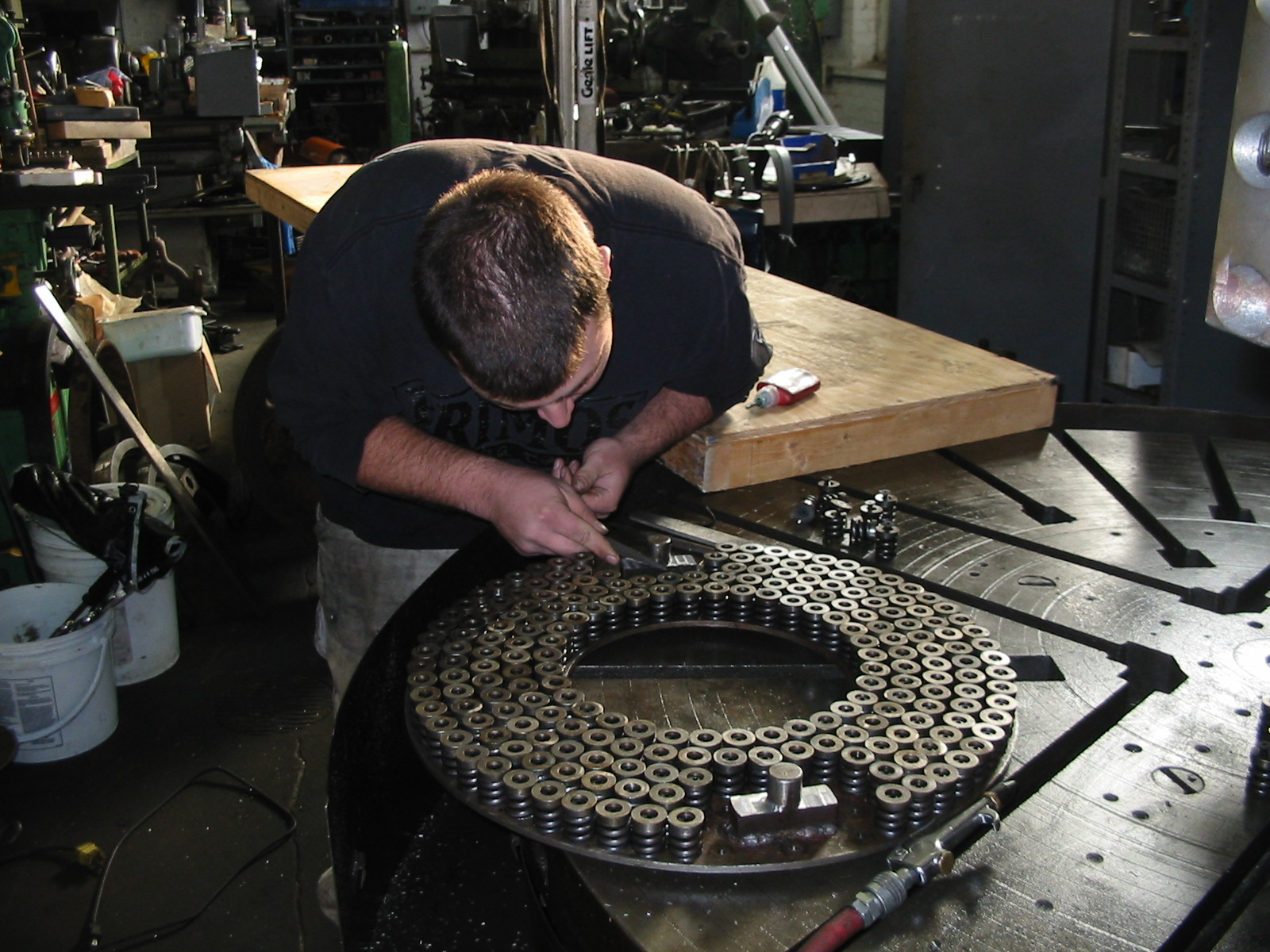
GE Springbed bearing having new springs installed.
New sleeve being tapped. This was used to repair a thrust block.
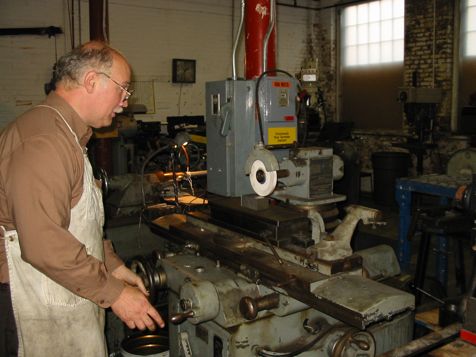
Surface grinding a height gauge.
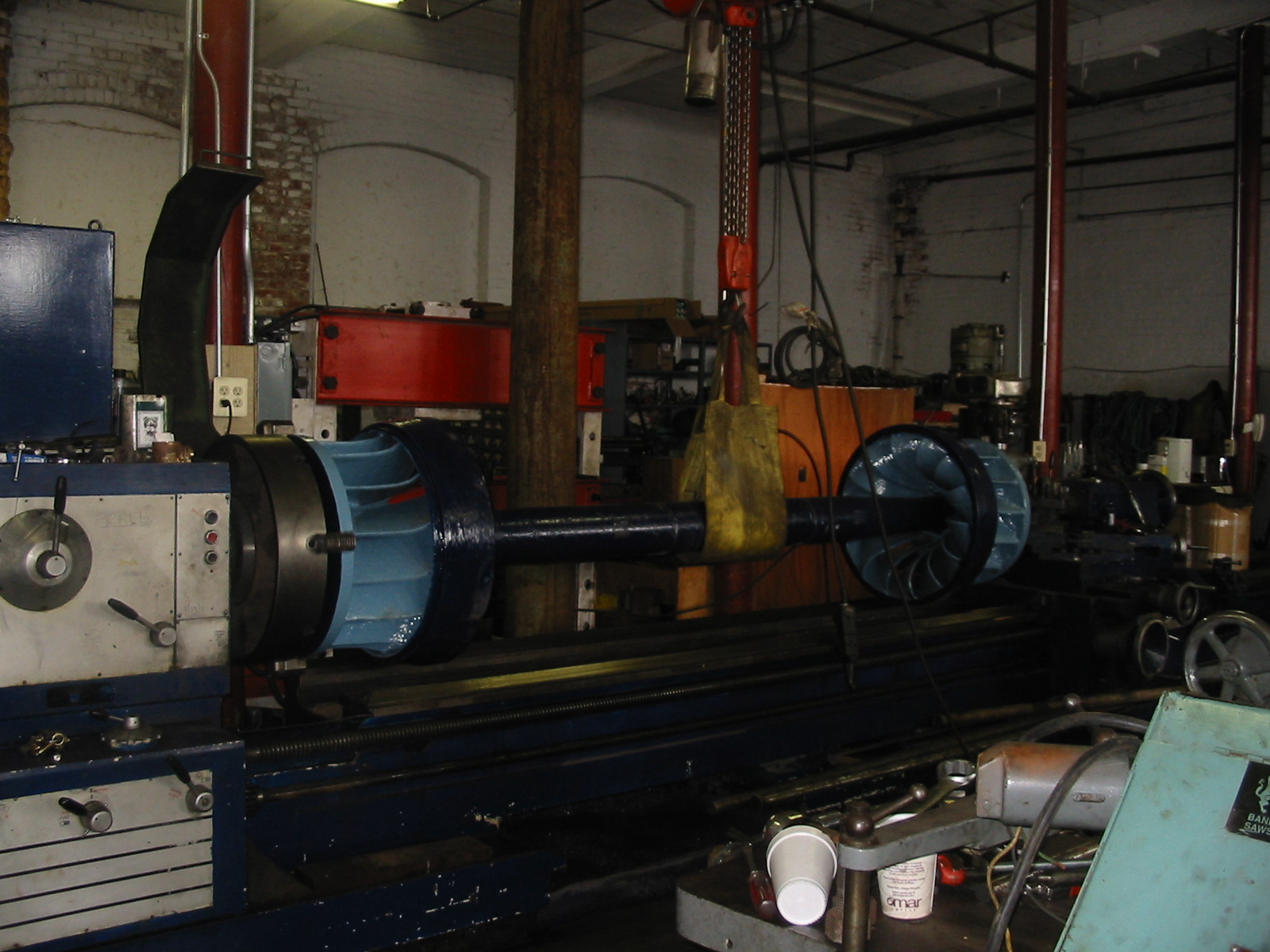
A pair of 24 inch Leffell, LL runners, on a common shaft, having their lignum vitae bearing journal turned true in the Poreba lathe.
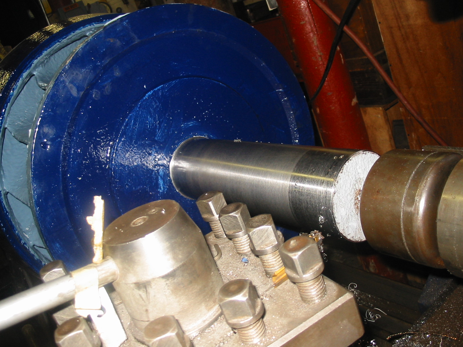
Newly turned journal for wooden, lignum vitae, underwater bearings
The Wizard turning Centennial Island's 60 Inch S. Morgan Smith, 800 KW GE slip rings.
An eight inch diameter, by 14 foot long, intermediate shaft for Pepperell Hydro's No. 2 Turbine.
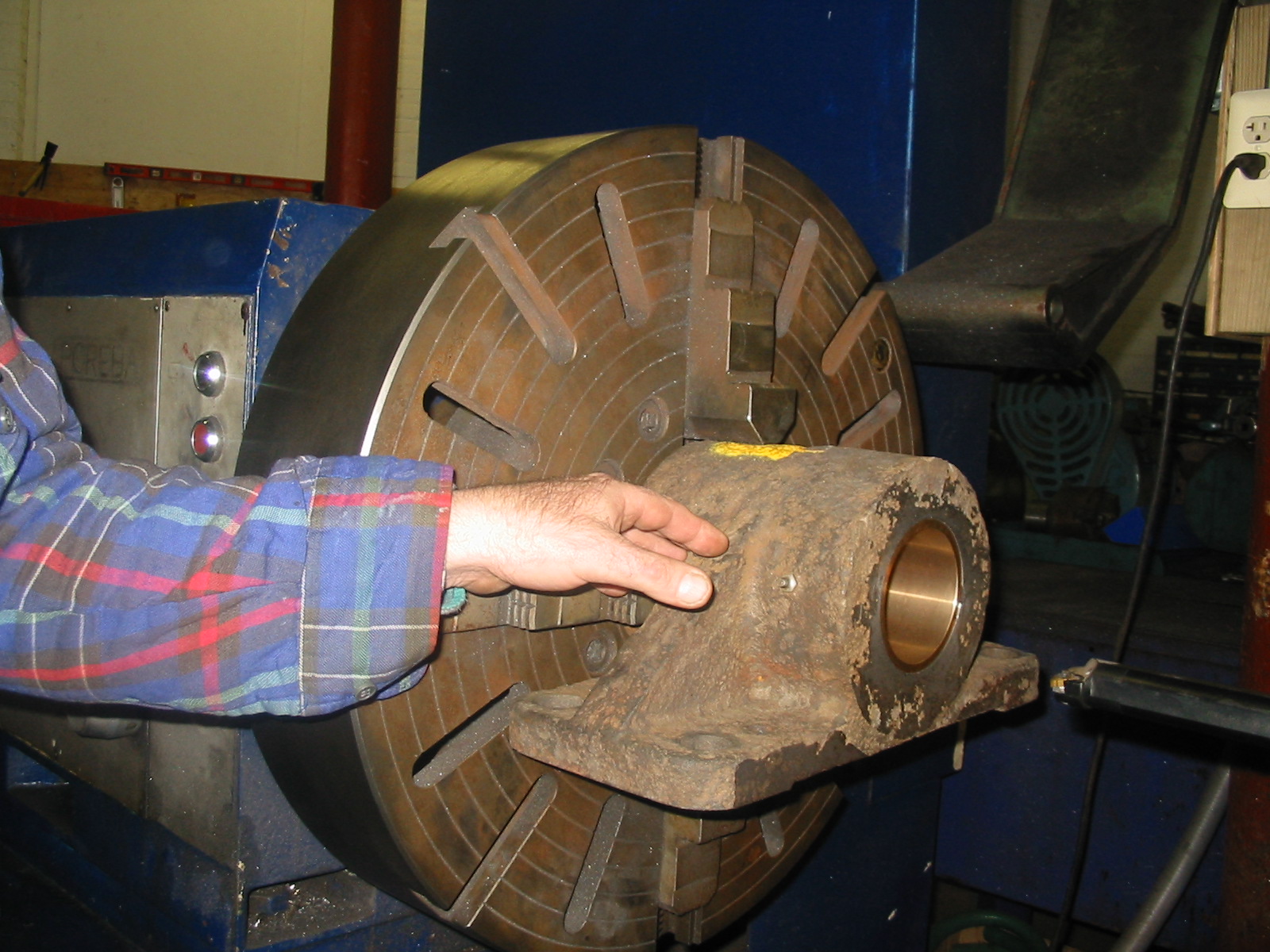
A new bronze bushing was installed in the Woronoco No. 2 governor shaft, pillow block. The bushing is being turned to fit the shaft's journal.
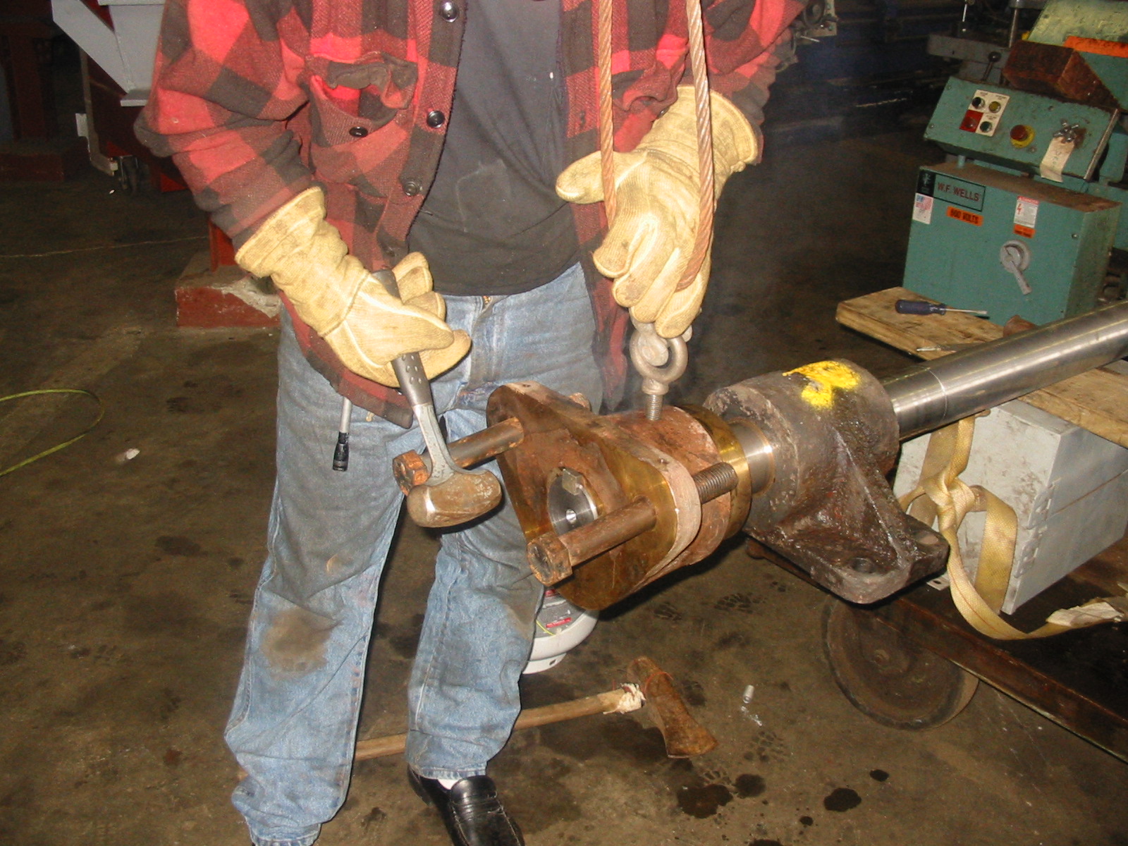
The cast iron, double bell crank, for Woronoco No.2's governor shaft had an ear broken off. We decided to replace the shaft, pillow block bushings and double bell crank. We had Royalston Arts Foundry in Royalston, MA cast a new double bell crank in bronze. The Wizard made a new shaft, fitted new bronze bushings in the pillow blocks and machined the new bronze double bell crank. Here he has heated the crank to 700 deg. F and is tapping it onto the new shaft.

A new wicket gate for the 39 inch Leffel B, Pepperell Hydro's No. 2 unit is being machined. We made 24 of these replacement gates.
Repairing a 14 inch main shaft on 4000 HP turbine by sleeving over the corroded section of shaft.
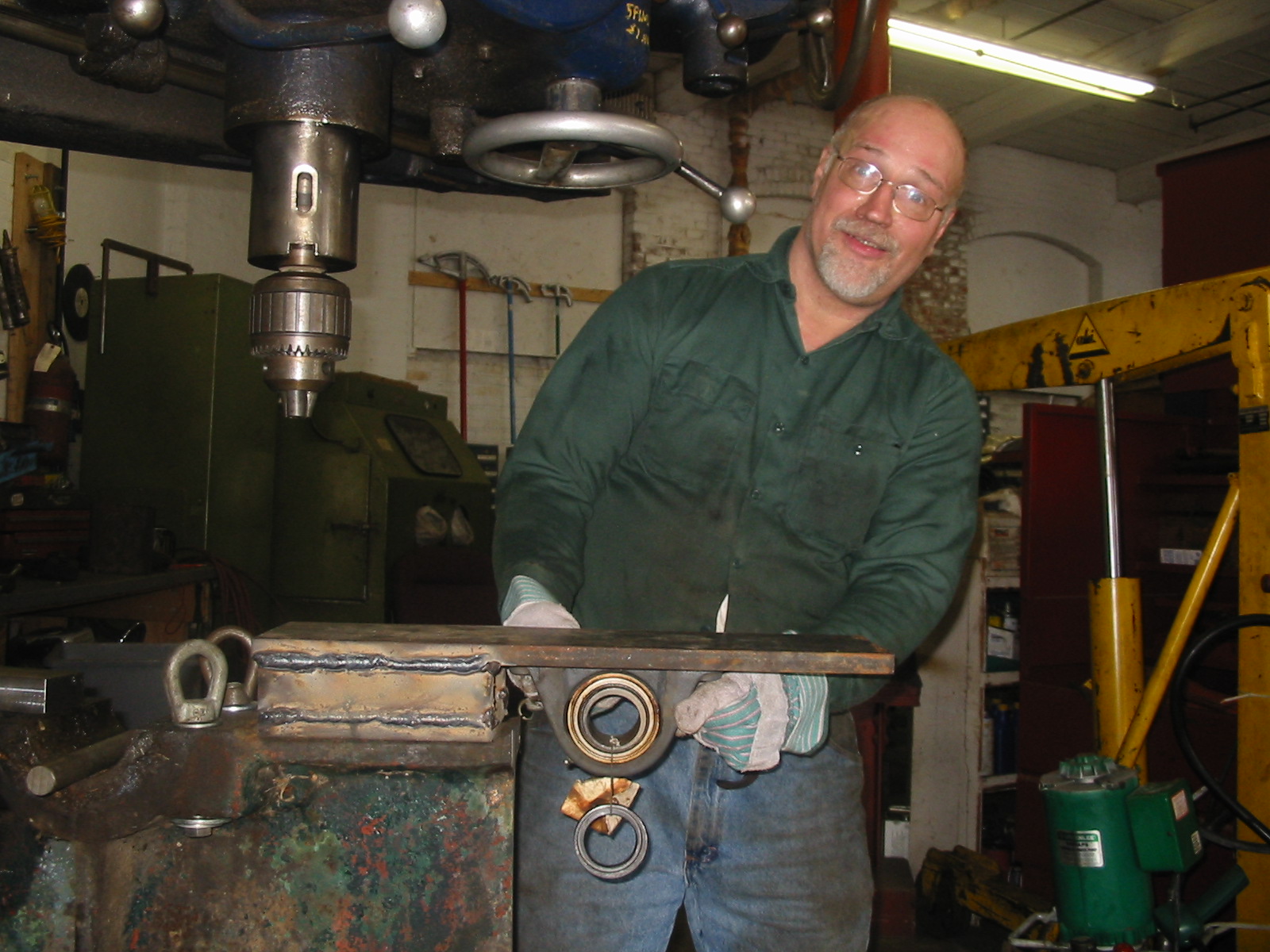
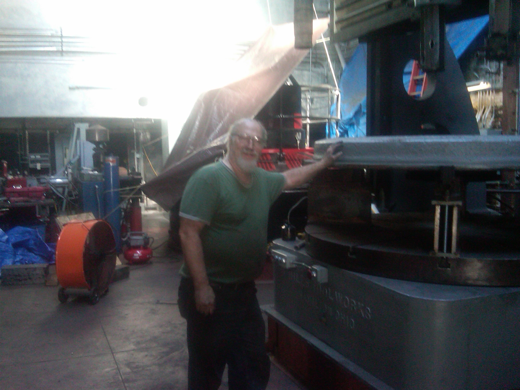
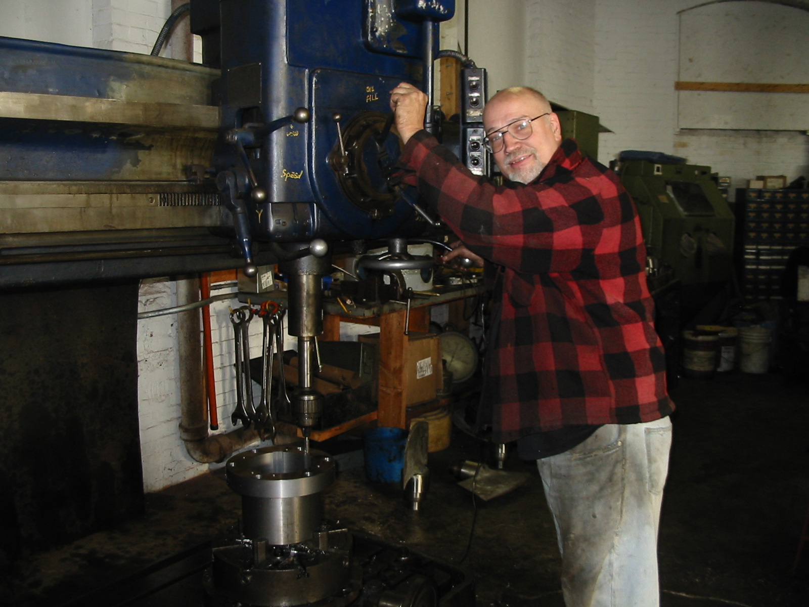
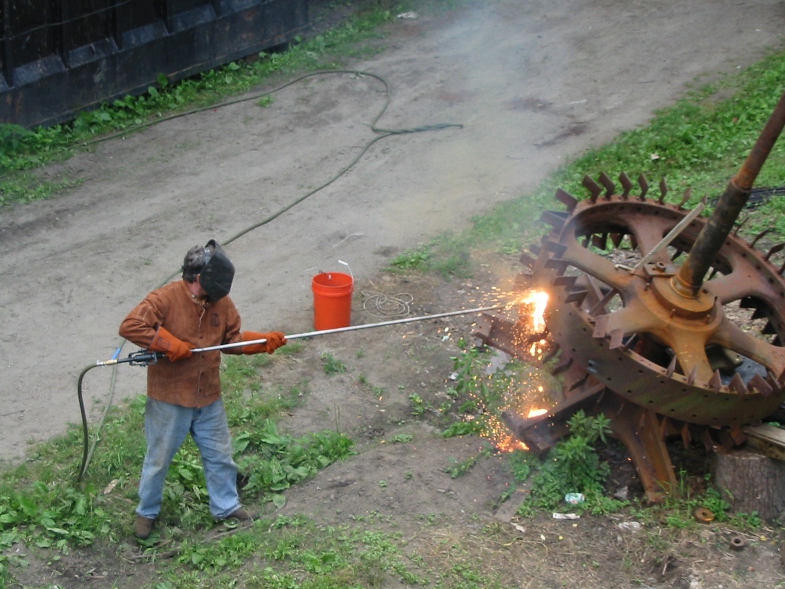
A gate stand, for the bull gear shown in the previous photo, had to be repaired. The wooden gate this gearworks operates is 12 feet high by eight feet wide by eight inches thick. The gate weighs approximately 1200 pounds, without the water pressure pushing against it. The operator pulled the safety pawl and allowed the gate to drop from its fully open position. The weight of the gate drove the gear train very fast. When the gate hit bottom and all that rotational mass came to an instant stop the forces were extreme. The end of the cast iron gate stand broke off and fell into the lake. Here the Wizard has machined the top and front surface smooth. He has fabricated a weldment with an under hung, pillow block, ball bearing to replace the missing piece. (Note the size of the mainshaft bearing to the left of the lifting eyes.) He has the piece in the large radial arm drill and is drilling and tapping the holes to hold the weldment to the cast iron stand.
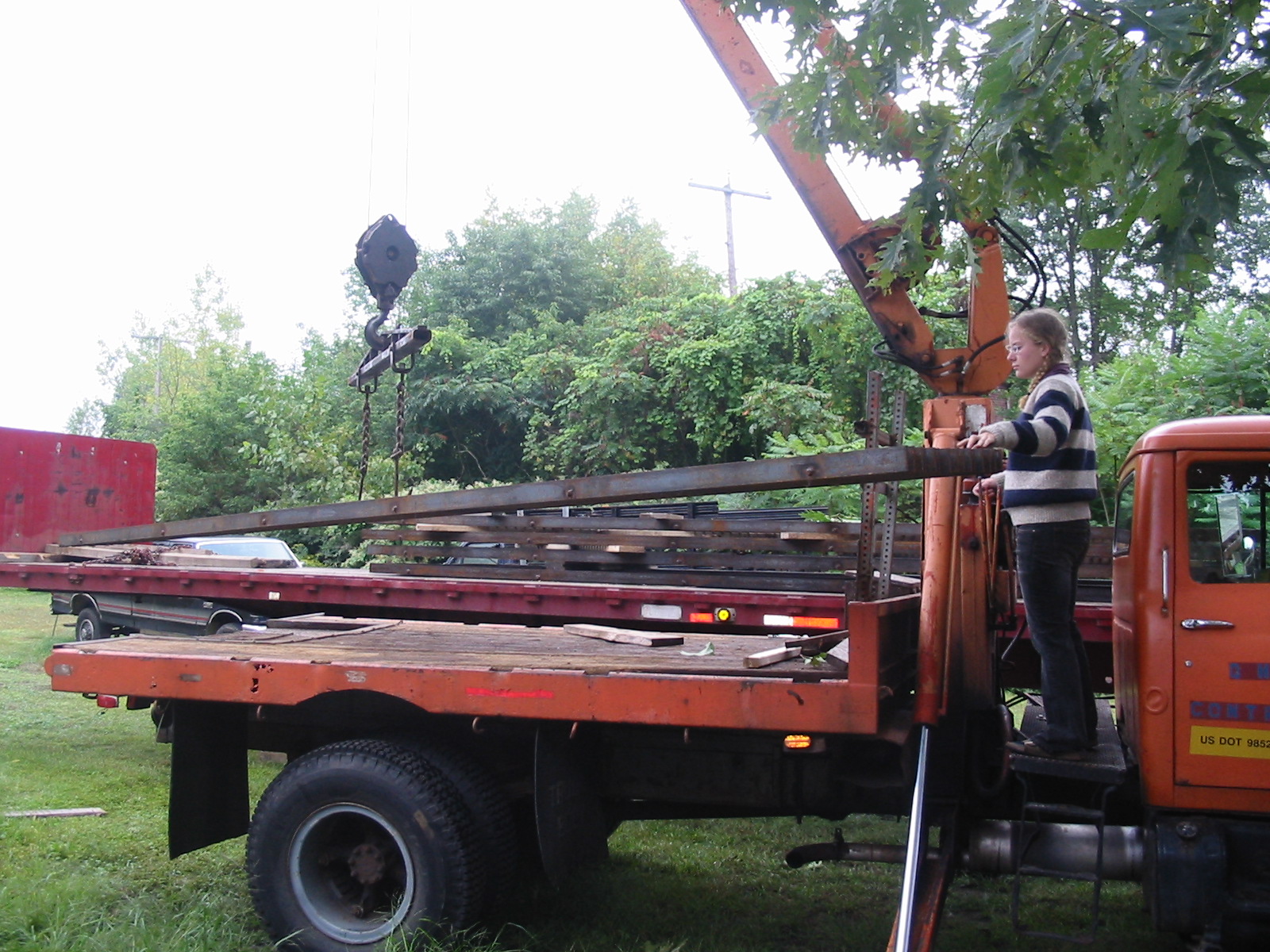
Celesty is loading the new trashracks for Pepperell No. 2, onto the flatbed, to take to Pepperell. We have tried various designs for holding the rack bars together and equally spaced. This time we used the metal worker to punch holes in the flat stock with an alignment jig. Next we assembled the individual pieces in a wooden jig and drove round stock through the punched holes. We welded every punched hole to the round stock.
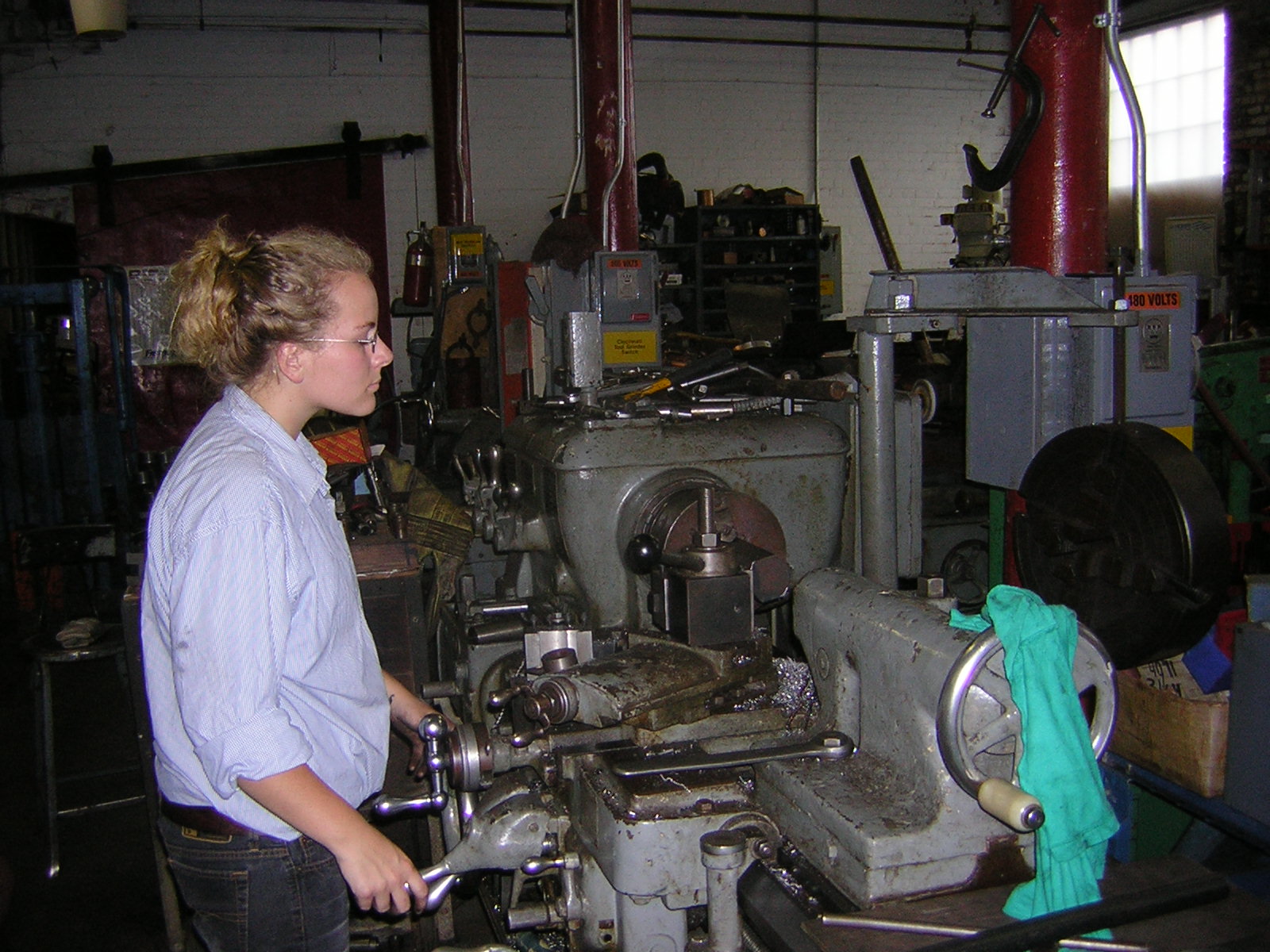
Celesty is making upper bushing nuts from a piece of hex bar stock for the Pepperell No.2 turbine.
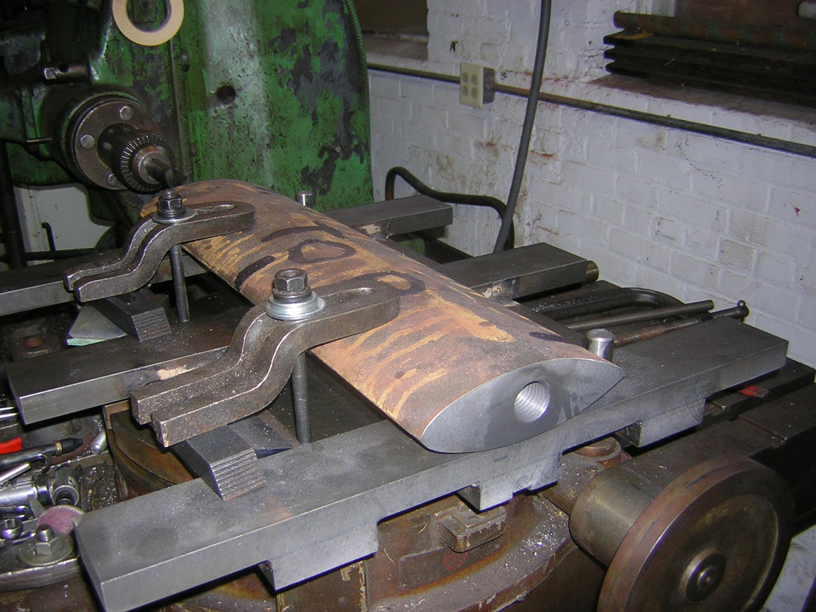
A new stay vane is being drilled and tapped in the Lucas boring mill.
Celesty and the Wizard finishing up the alignment of the main gear train, at the Slater Museum, in Pawtucket, R.I. Museum staff complained for years that when the exhibits ran off the breast wheel that their desks would shake!! Finally they turned the breastwheel off, installed an auxilliary motor and ran the exhibits with electricity.
To align shafts, one takes a dial indicator with a magnetic base and puts the base on the radius of one shaft. With the shaft coupling disconnected, the pointer of the dial indicator is placed on the radius of the other shaft. You turn the shaft with the base around. If the shafts are concentric, the dial indicator pointer will not move. If the shafts are eccentric, the indicator will tell you the amount of misalignment. When we indicated the Slater Mill shaft it was out by a 1/8 of an inch!!
Unfortunately the bearings were installed in chiseled pockets in the main floor beam. We had to get our wood chisels out, modify the pockets, and move the bearing until it was aligned. This made the holes in the wrong place. We filled the holes with wooden plugs and drilled new ones in the correct location. When we were done and the machine was running with no vibrations, one of the staff came in and wanted to know when we would be done so that they could run the exhibits with the re-conditioned breastwheel. To their amazement, the wheel was already quietly running.
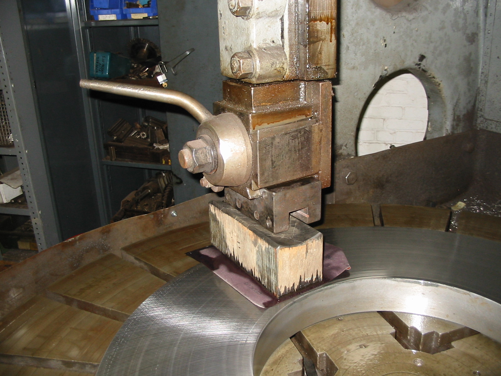
The Kingsbury thrust plate, for the main bearing, for Pepperell No. 2. was pitted. We had Riverside Machine, in Holyoke, MA, resurface the plate with a Blanchard grinder. The tolerance achieved was 40 microns (40/1000000) of an inch. We needed to achieve 20 microns or less. Here we have mounted the plate on the 60 inch Bullard and we are polishing it with crocus cloth and WD 40.
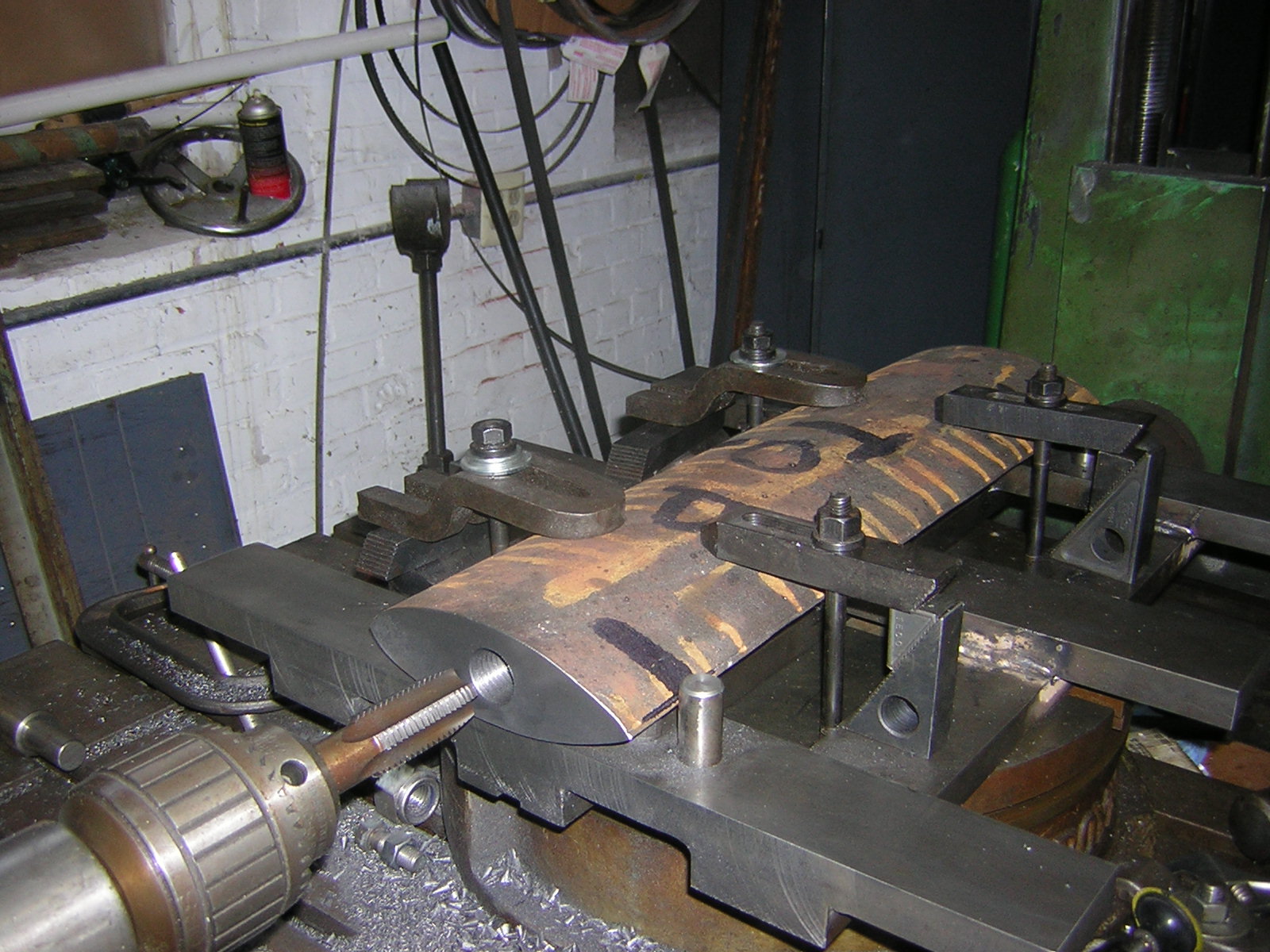
One of the stator feet, for the No. 2 Unit, at Pepperell was missing when we purchased the used generator. The Wizard made a duplicate foot. Here he is turning the bottoms of all four feet so they match in height.
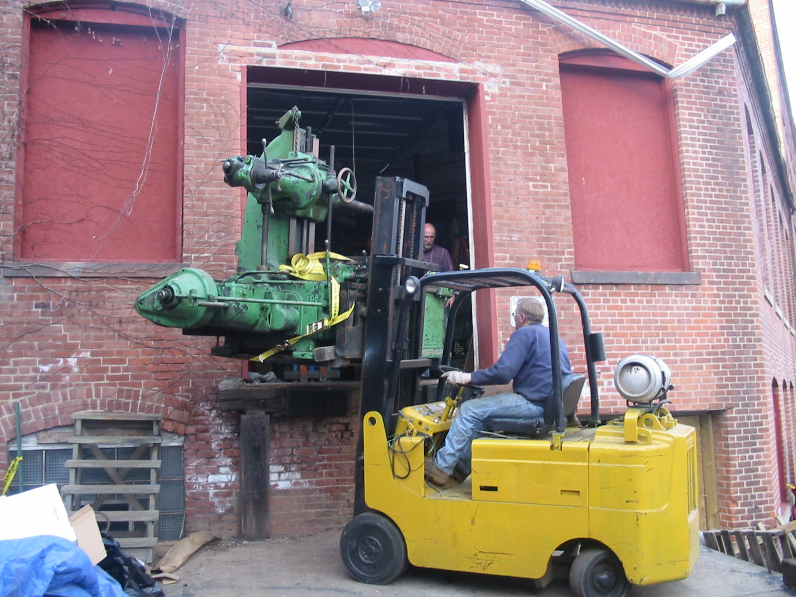
The Lucas boring mill getting stuffed through the door of the shop. This was taken right before we realized it was not going to fit through the door orientated this way!
And this was taken about four hours later. We had to load it back on the truck, crib the truck deck up and pull it into the shop.
Grinding slip rings for Consolidated Edison's Indian Orchard Plant. We now do this job on the 60" Bullard.
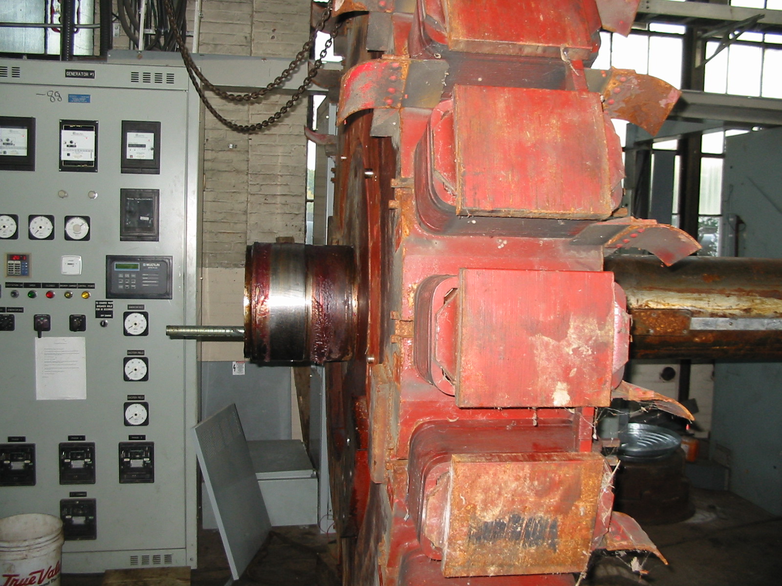
Here, I am using a thermite bar (tip temperature is 14,000 deg F, oxy acetylene torch maxs out at 2500 deg F) to burn the rotor, of the carcass, of the Westinghouse generator. We needed the shaft, lower radial bearing and spyder to replace the missing components of the Dong Fang Generator. We were afraid to press off the shaft because it had sat too many years in the weather. We modified the shaft to press into the Dong Fang generator's hollow core. We burned the lower half of the Westinghouse stator off to create a bed ring for the Westinghouse stator. Note the molten cast iron and gaseous iron. Kids don't do this at home!!!
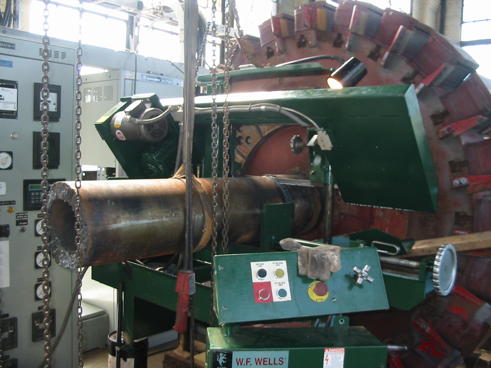
We had to cut the 12" shaft on the Dong Fang generator. We stole the Wells cutoff saw from the Wizard, welded threaded rod legs to it, slid it over the shaft and cut the shaft off.
Here is the cut off shaft. The Chinese would be horrified.
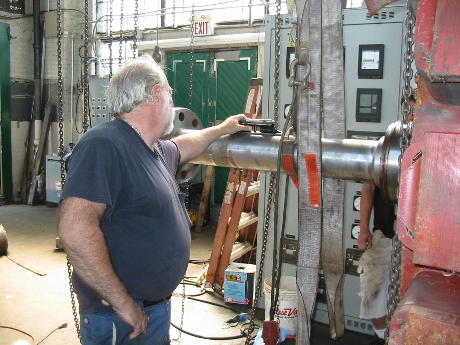
Here, we are inserting the cut off Westinghouse generator shaft into the hollow (former Kaplan turbine) Dong Fang generator shaft. We are combining the carcass of the Westinghouse generator with the Dong Fang generator. Is it a Dong House or a West Fang?!!!
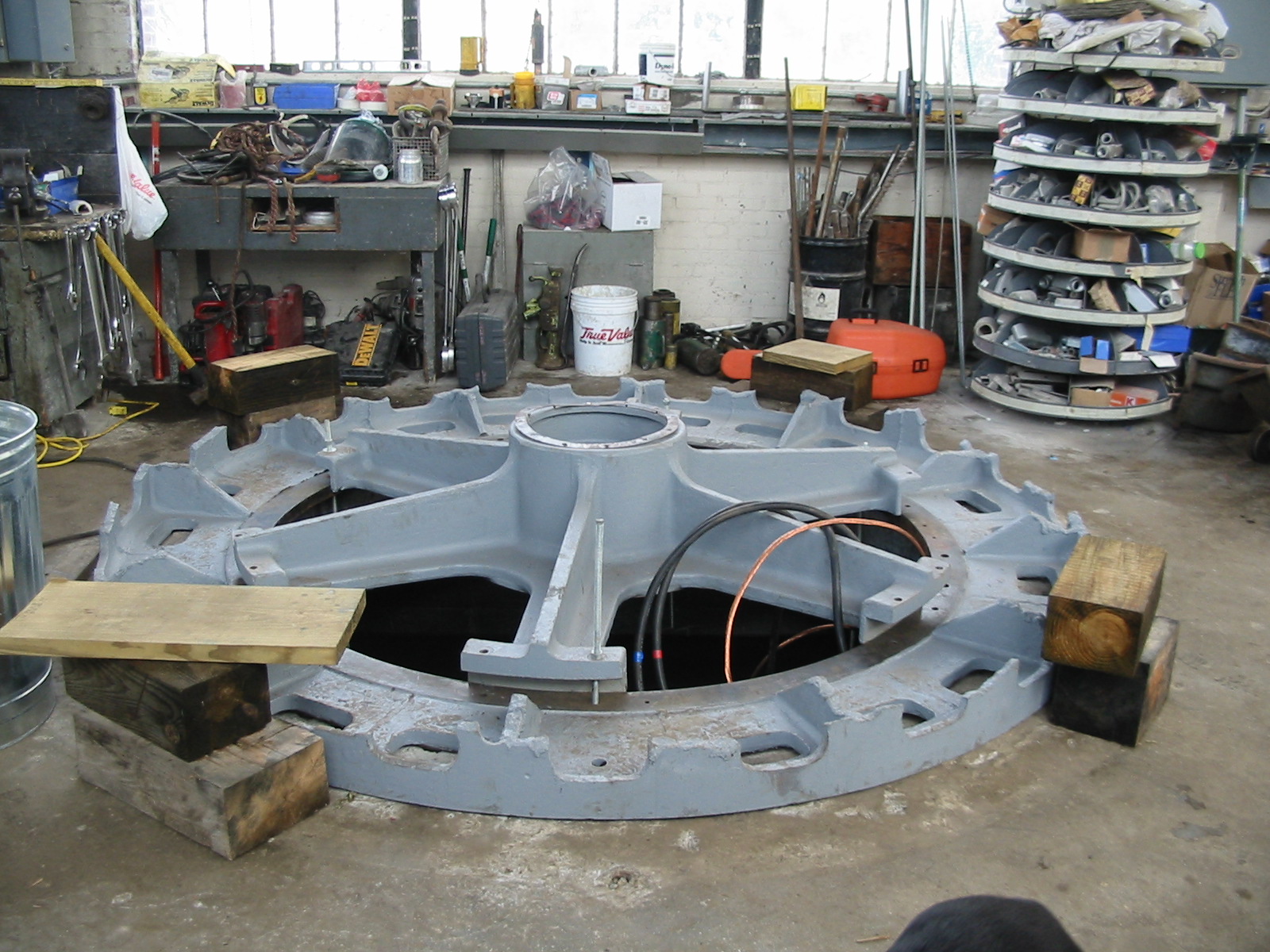
We needed a replacement for the missing Dong Fang spyder and lower radial bearing. We used the thermite bars to cut off the bottom of the Westinghouse stator. We positioned it over the No. 2 pit, as a bed ring, for the Westinghouse spyder and lower, radial bearing. This assembly matches the Westinghouse shaft that we pressed into the Dong Fang generator. The outside diameter of the Westinghouse stator carcass fits inside the inside diameter of the Dong Fang stator. Note the odd castellations that are the edges of the former ventilation portholes of the Westinghouse stator.
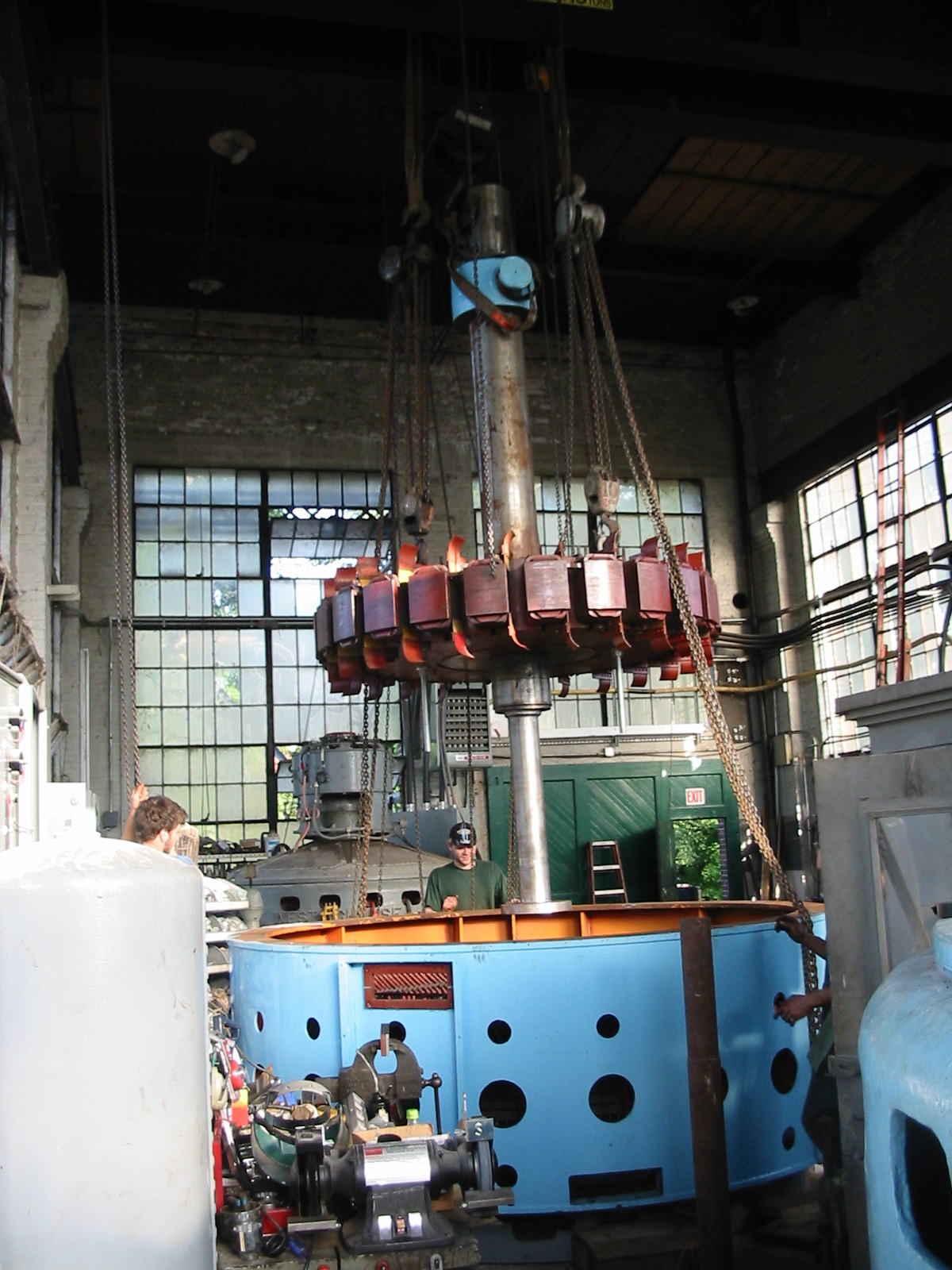
Here, we are flying the 24,000 pound rotor into place in the Dong Fang Stator. Note the Westinghouse shaft inserted and pinned into the Dong Fang rotor. Unit No. 1 is in the background. Note the re-configured, cutoff, Westinghouse stator and lower bearing is positioned under the blue Dong Fang stator.
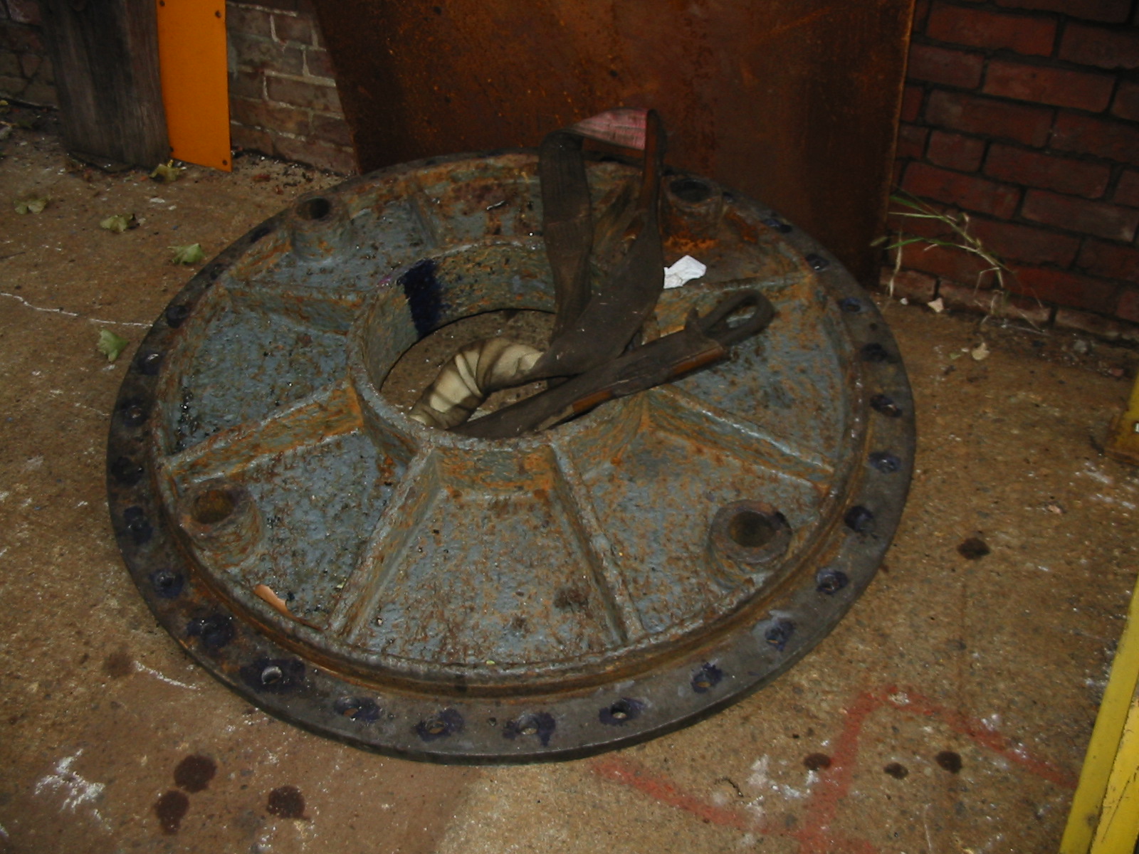
This is the cast iron head cover for a unit from Vermont. It was cracked and, due to the high head it was installed on, the owners wanted a new one made.
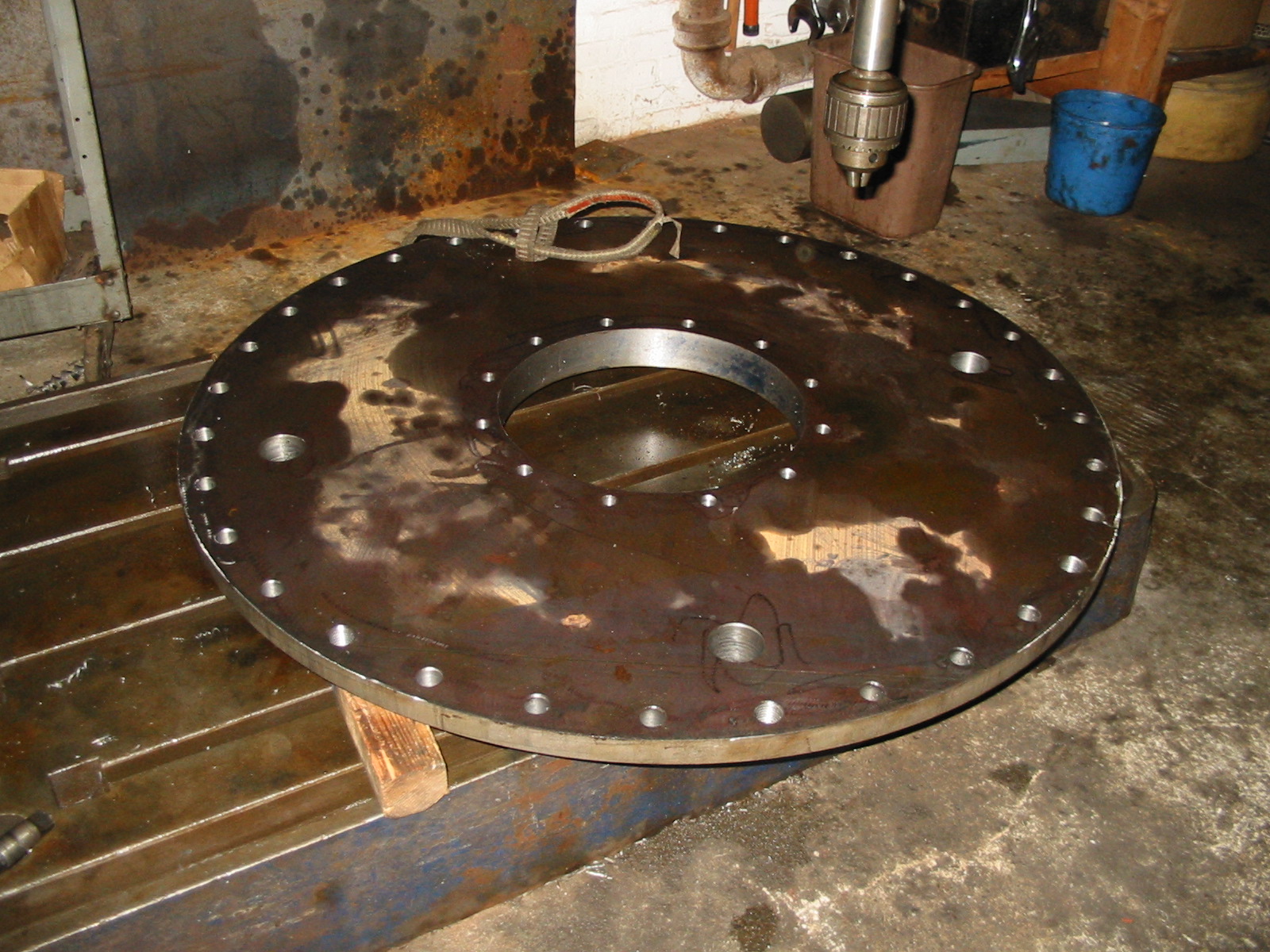
Here is a new headcover which the Wizard made from a solid steel plate.