Bradway Turbine Webpage
Charlie Bradway invented a unique gate system that tried to achieve increased part gate efficiency. You should refer to the following photographs and trade catalouges. His gate system had 16 gates. The fixed guide vanes were thicker than normal vanes. The guide vanes were cast to an upper plate and a lower ring. In between each guide vane he bored a cylindrical hole. The holes were located so that they were recessed more into one guide vane than the other. He placed a cylindrical slug into the hole. The slug had 80 percent of its mid range removed. When you turned the slug one way, the opening was closed off. When you turned it the other way, the partial cylinder, recessed into the guide vane and allowed the water to pass between the guide vanes. The actuator was quite ingenious. On top of the cylindrical slugs (cast integral) was a tuning fork. There were eight gates with a low tuning fork and eight gates with a high tuning fork. The gates were placed in the 16 holes, in an alternating pattern, with all the tuning forks pointing in the same circumferential direction. A shift ring with four, long, bronze pins, 90 degrees apart and facing downward was located on the top of the gate case. As you rotated the shift ring, the pins engaged the first four of the tuning forks. As you continued to turn the shift ring, the forks were flipped, 180 degrees around. The first set of forks were low and they turned beneath the next four forks that were taller. The water flowed through 1/4 of the gate case (four out of sixteen gates were open). Now as you continued to turn the shift ring, the four pins engaged the next set of forks (these were the taller forks). They were similarly flipped 180 degrees and 1/2 of the gate case was opened. The shift ring was continued to be rotated until all 16 gates were open. The advantage to this system was that at the 1/4, 1/2, 3/4 and fully open positions, the vector triangle relation on the running turbine was matched. He really did achieve part gate efficiency.
In 1979, as the newly hired Chief Engineer of Ware River Power Company (the only engineer!!!) my first project was the reconstruction of the hydroelectric light plant, of the Warren Coprporation, in Stafford Springs, CT. When we finally got the site dewatered and opened the pressure case we found a Bradway turbine. The gates were quite rotten and the tuning forks were badly corroded. I made a mechanical drawing of the gate. We had a pattern made. I took the pattern to the Ware Foundry in Ware, MA. This ancient old man came into the front office to see what we wanted cast. To our astonishment, he said, "That's a gate for a Bradway turbine." We asked how he knew that. He told us that his first job ever at the foundry, when he was 12 years old, was to assist the foundry man to make Bradway turbine parts!!
Hello.
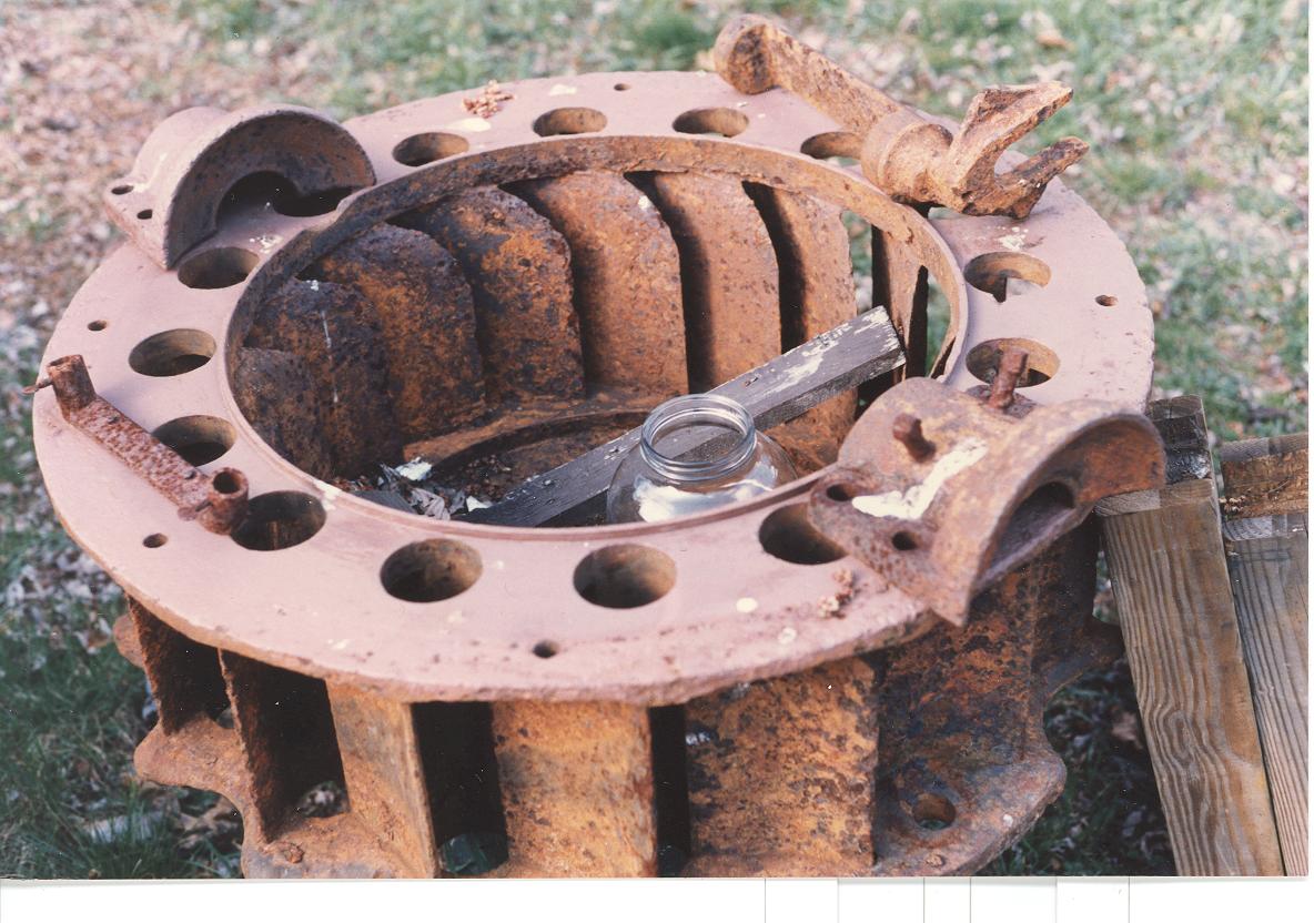
This is a great picture of a dismantled gatecase. It is upside down. Note the 16 holes and the fixed guide vanes. Note the Bradway gate with its classic tuning fork and the semi-cylinder that it turns. This gate is one of the eight with the low tuning fork.
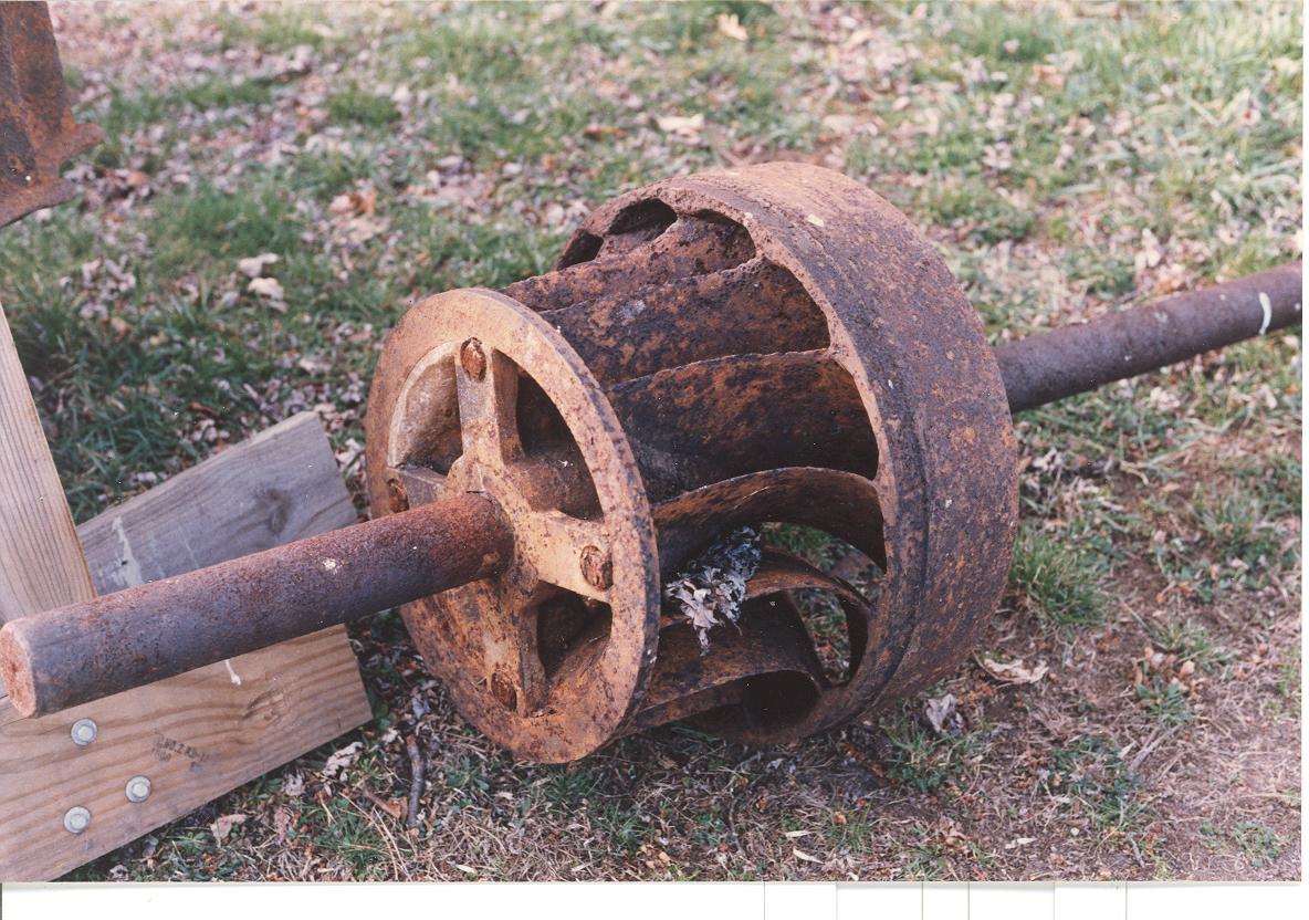
Bradway turbine runner.
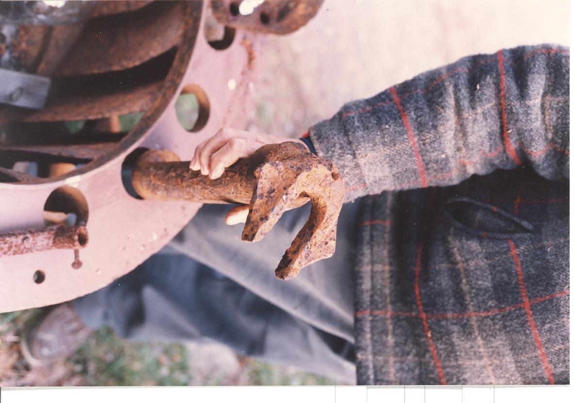
This picture is incorrect. The tuning fork/semi-cylinder is actually inserted from the other end.
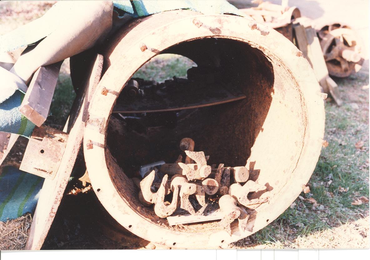
A pile of Bradway gates sitting inside a Bradway pressure case.
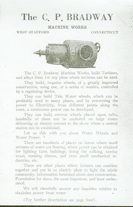
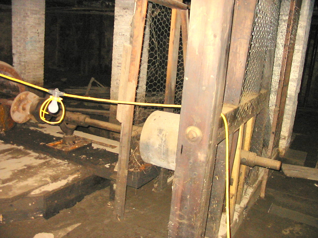
One of Charlie Bradways turbines just waiting for rehabilitation.
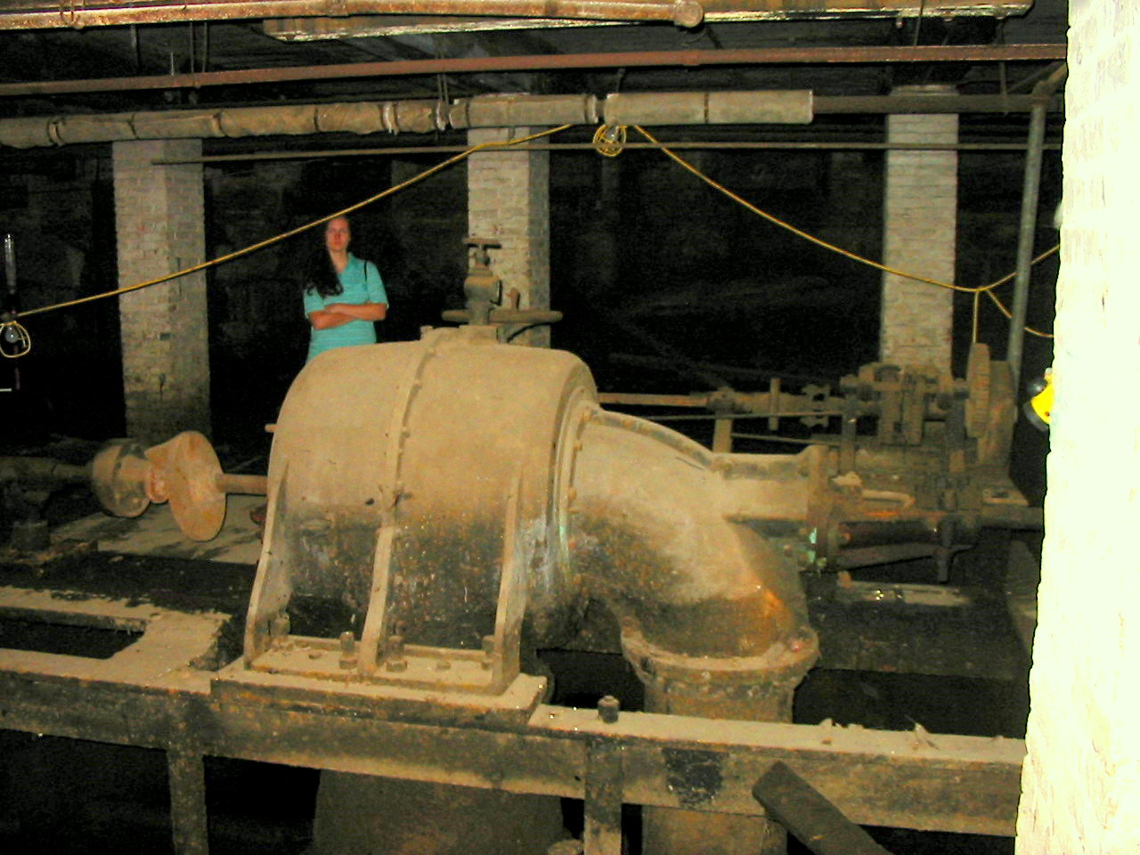
Poor Mary! Will drags her into a dirty mill cellar.
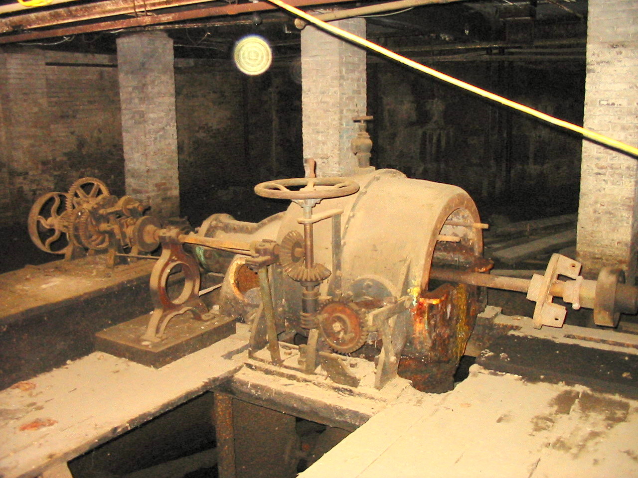
This an actual Bradway Waterwheel Governor.
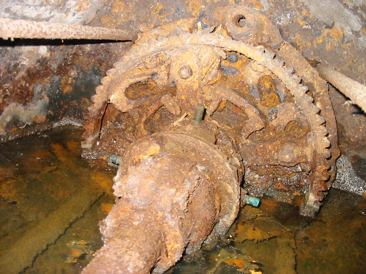
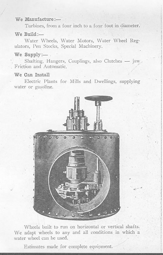
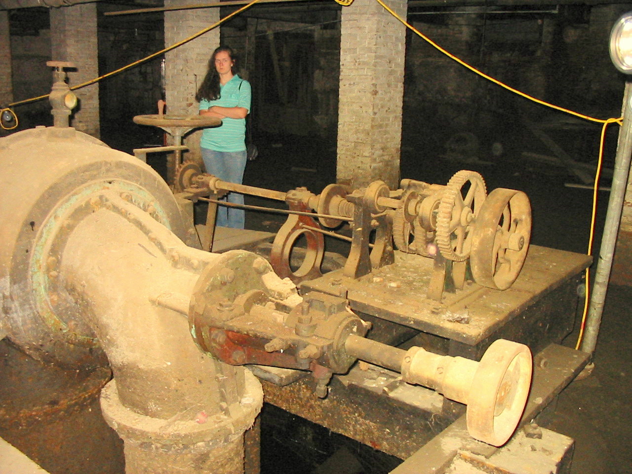
Here is a view looking in the end of the pressure case. Notice the bull gear with one of the large pins (nut on top) used to flip the tuning forks. You can see some of the tuning forks beneath the rust.
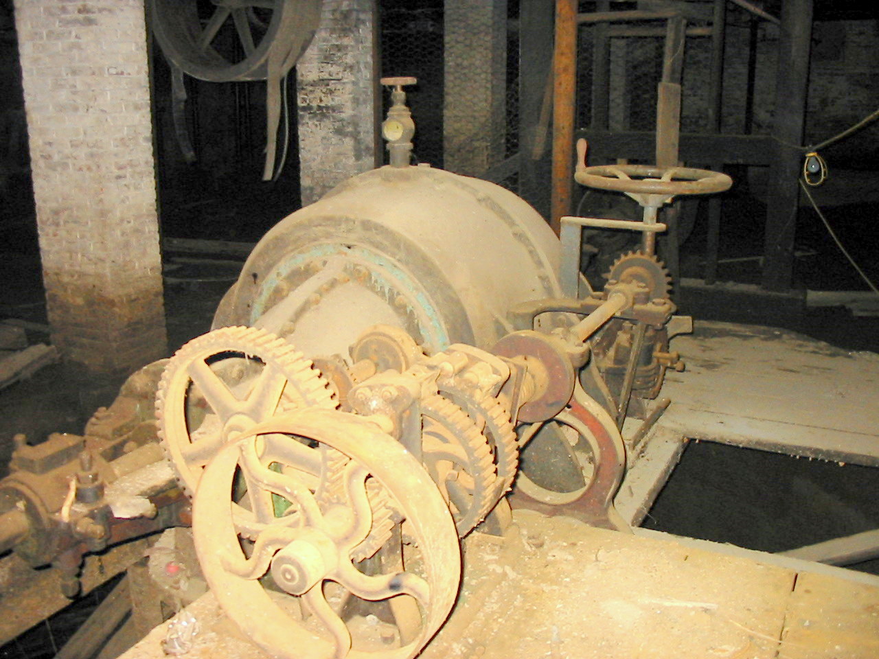
Another view of Charlie's governor.