Sparhawk Mills Web Page
POWER PRODUCTION STUDY
OF THE
SPARHAWK MILLS HYDROGENERATION FACILITY
AT
YARMOUTH, MAINE
AUGUST 2007
Prepared by:
FAY ENGINEERING SERVICES
P.O. BOX 624
THORNDIKE, MA. 01079
Phone 1-413-427-2665
Fax 1-413-283-4741
E-mail:
wfay@frenchriverland.com
TABLE OF CONTENTS
I) EXECUTIVE SUMMARY 3
II) INTRODUCTION 4
III) PROJECT DESCRIPTION 5
IV) SITE VISTIT 6
V) HYDROLOGY 7
VI) PROPOSED POWERHOUSE LOCATION 11
VII) WATER SURFACE ELEVATIONS 13
VIII) MODEL METHOLOGY 15
IX) RESULTS 16
X) DISCUSSION 18
XI) RECOMMENDATIONS 20
XII) BUDGET 21
APPENDICIES 22
I) EXECUTIVE SUMMARY:
A detailed, computerized, daily model was used to predict electrical production at Sparhawk Mills Hydro Site for the installed turbine-generating units. The period of record, 1950 to 2003, was used. Since a USGS Gauge is located 1800 feet downstream of the project, direct flows from the gage were used in the model.
The average annual historic gross electrical production of the site, for 1950 to 2003 the average was approximately 938,000KWh.
A detailed cost analysis was preformed on the cost of completely rebuilding the two automatically adjustable Hydrolec H-9-H turbines and the one manually adjustable Hydrolec H-9-H turbine. The cost to rebuild the two automatically adjusting turbines is $76,300 or $38,140 per turbine. The cost to rebuild the manually adjustable turbine is $38,140. The total cost to rebuild all three turbines is $ 104,300.
II) INTRODUCTION:
John Carroll has hired Fay Engineering Services (FES) to make an energy production study and generating equipment repair/overhaul pricing of its hydroelectric generating plant located at Sparhawk Mills in the Town of Yarmouth, Maine. For the purposes of this report, the existing equipment consisting of three Hydrolec H-9-H tube turbines was used to estimate the plants average energy production.
The production analysis is based upon a detailed, daily, production model of the site. It utilizes 53 years of United States Geological Survey's (USGS) stream flow data (1950 to 2003) from the USGS gauging station at Yarmouth, Maine. This gauge is located 1800 feet downstream of the Sparhawk HEP on the Royal River. No tributaries contribute to the Royal River’s drainage area below the bridge street dam and above the USGS gaging station. Therefore the USGS gage data can be used directly in the model without drainage area modification factors.
Gage # 01060000 is located on the right bank, 2.325 river miles upstream of the Royal River’s confluence with Casco Bay. The drainage area at the gage is 141 square miles. The average discharge for fifty three years is 272 cubic feet per second (cfs).
The recorded daily average flows at the gage can be used to construct a matrix of flows for the period of record. This data can be input into a computerized production model to accurately predict the sites annual electrical production.
The number one and the number two units have been recently rebuilt by the current owner. The third unit will need to be rebuilt in order to put it back online. A complete rebuild of the unit three machine is recommended due to the increase in reliability and reduction in environmental liability due to oil leaks. Further discussion of the rebuild is addresses later in this report.
III) PROJECT DESCRIPTION:
The Project Dam is called Bridge Street Dam. It is located in the Town of Yarmouth, Maine, 200 feet upstream of the Bridge Street Road Bridge. Its coordinates are 43 degrees, 48 minutes, 05.49 seconds north and 70 degrees, 11 minutes, 04.01 seconds west. It drains approximately 141 square miles of drainage area, impounds a reservoir of 5.2 acres and stores 10 acre-feet at normal pool elevation of 41 msl. The height of the dam from its toe to the top of its abutment is 12 feet.
The project is a FERC exempted hydroelectric power plant, rated at 270 KW on 18 to 21 feet of head. It was originally constructed to provide manufacturing power to the mill located downstream. The original equipment fell into disrepair and was eventually abandoned. In 1984 a FERC exemption P-8417 was issued and the site was rehabbed with three new Hydrolec turbine-generators, a new penstock, new headworks, and dam repairs.
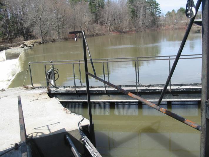
Figure One: Side View of Bridge Street Dam, looking at the spillway
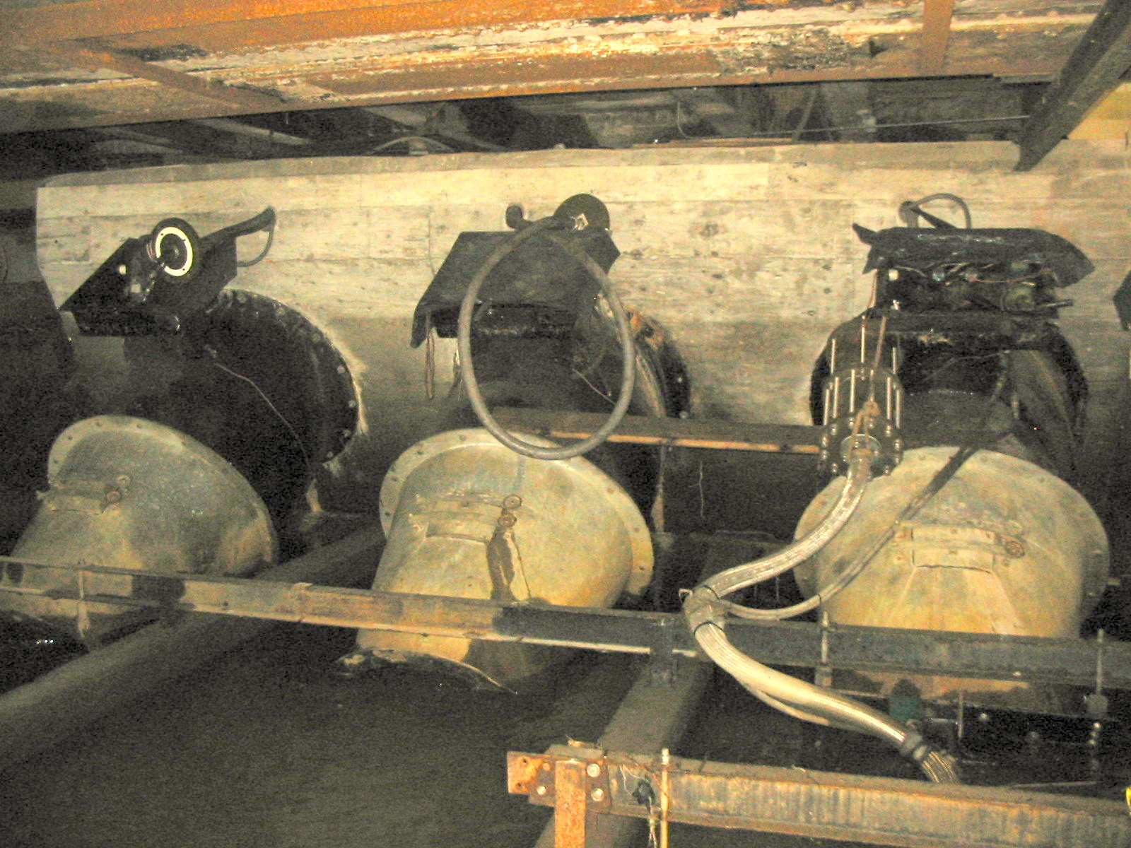
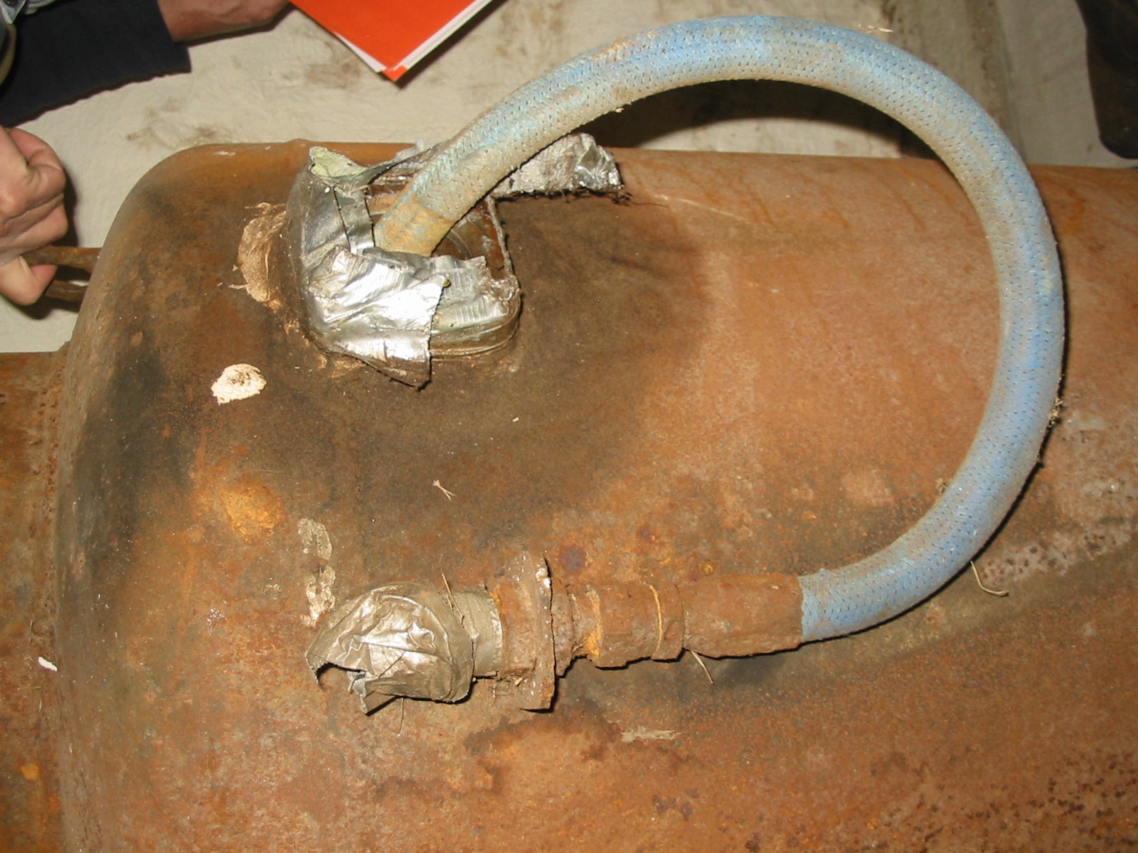
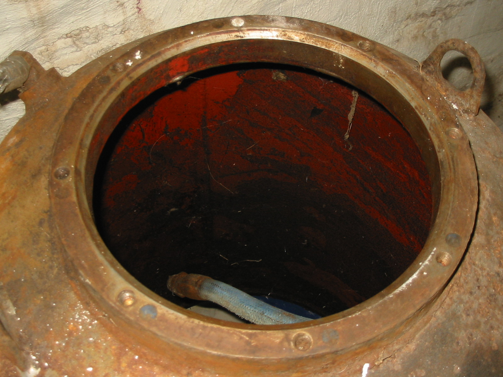
The appurtenant features consist of a one hundred and thirty five foot long, concrete-gravity spillway, a fish ladder, intake works for the penstock, penstock, powerhouse, and equipment. The Denali fish ladder is located at the spillways right abutment. The Maine Department of Marine Resources owns and operates the facility. A ten foot wide concrete walled intake is located in the dam’s left abutment. A 45 foot long fish screen prevents aquatic life from entering the intake area. A ten foot wide section of trash racks is mounted in the concrete intake structure. A head gate is located behind the trash racks to shut off flow to the penstock. The 7 foot diameter steel penstock is 200 feet long and runs from the penstock headworks to the equipment/generating room of the mill. The penstock is made of old rail road tank cars and appears to be in good condition. The penstock enters the mill and trifurcates for each of the three units. The trifurcations come through a concrete thrust block in the basement of the mill. Before the end of the trifurcations, each section has a 60" butterfly valve. At the end of each trifurcation is a bolted pipe flange, where the Hydrolec tube turbines are attached.
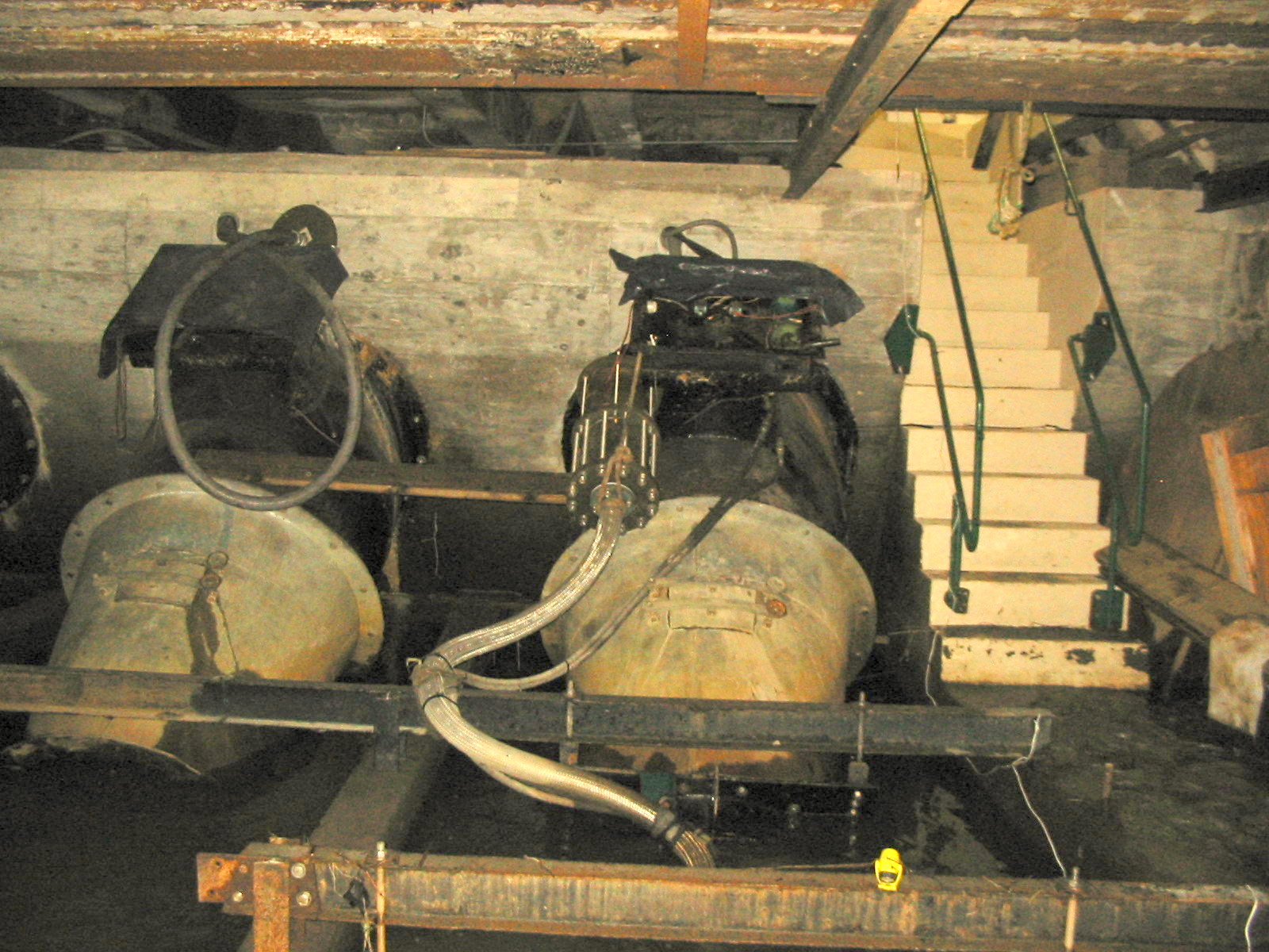
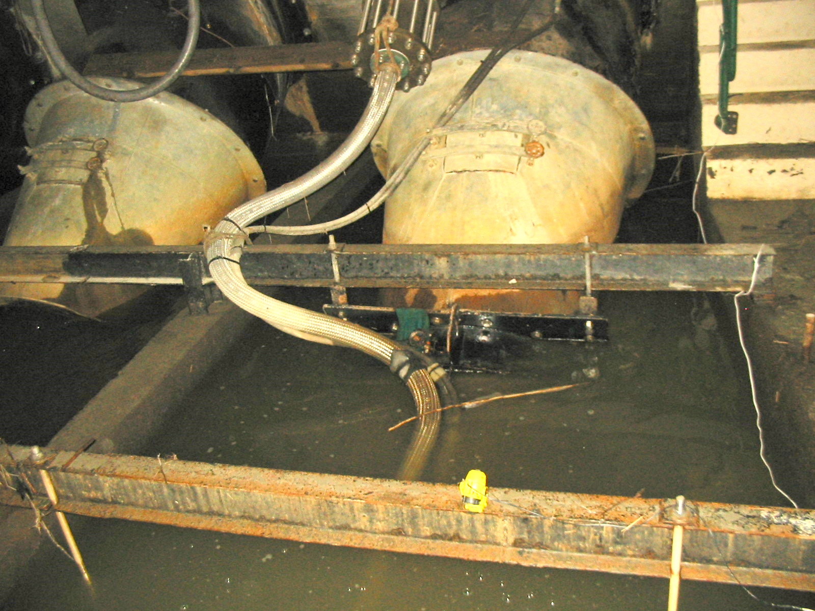
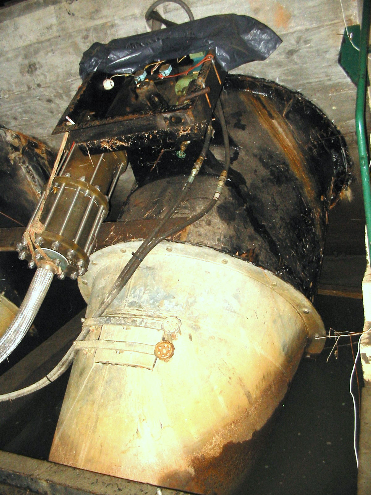
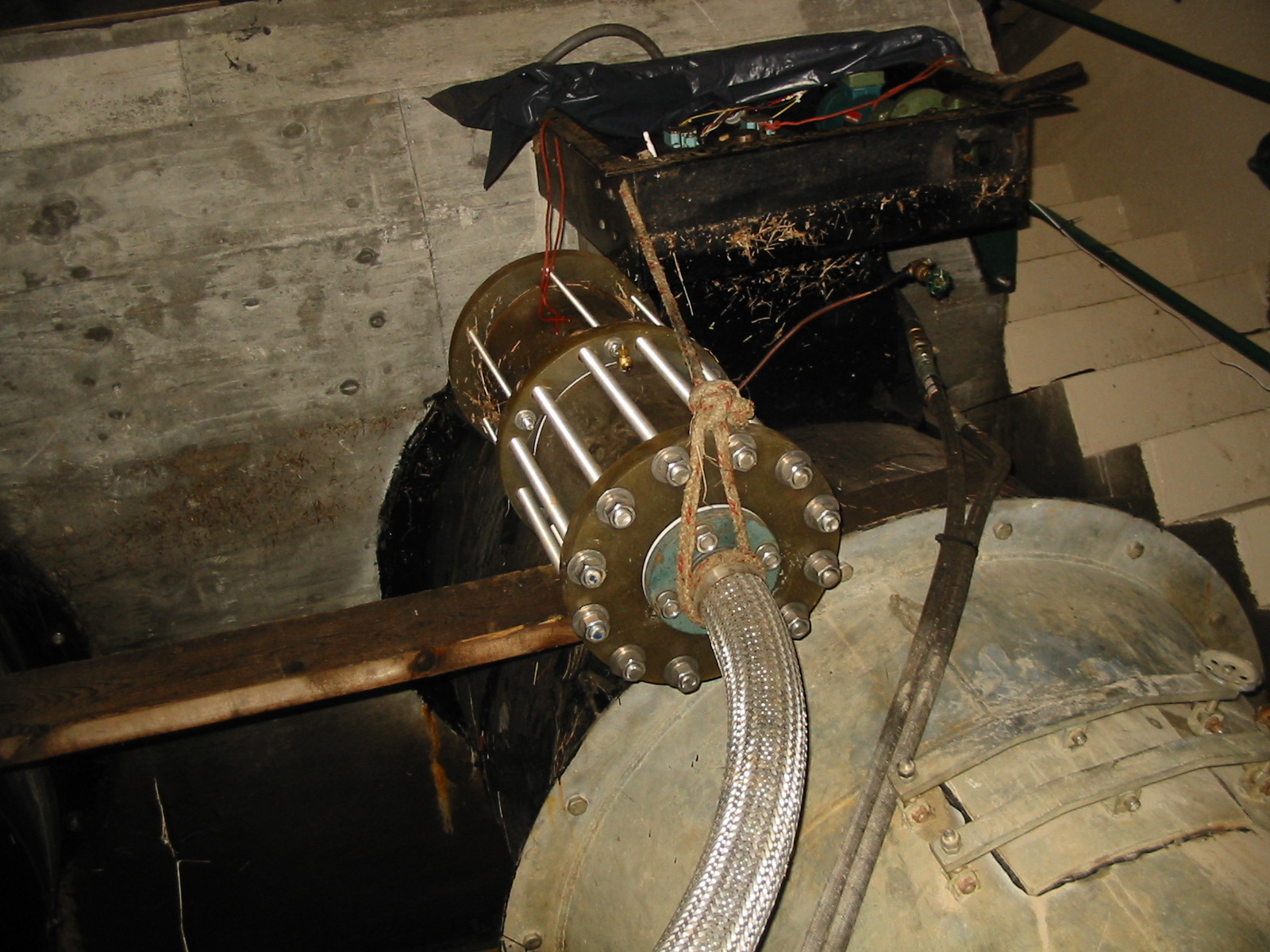
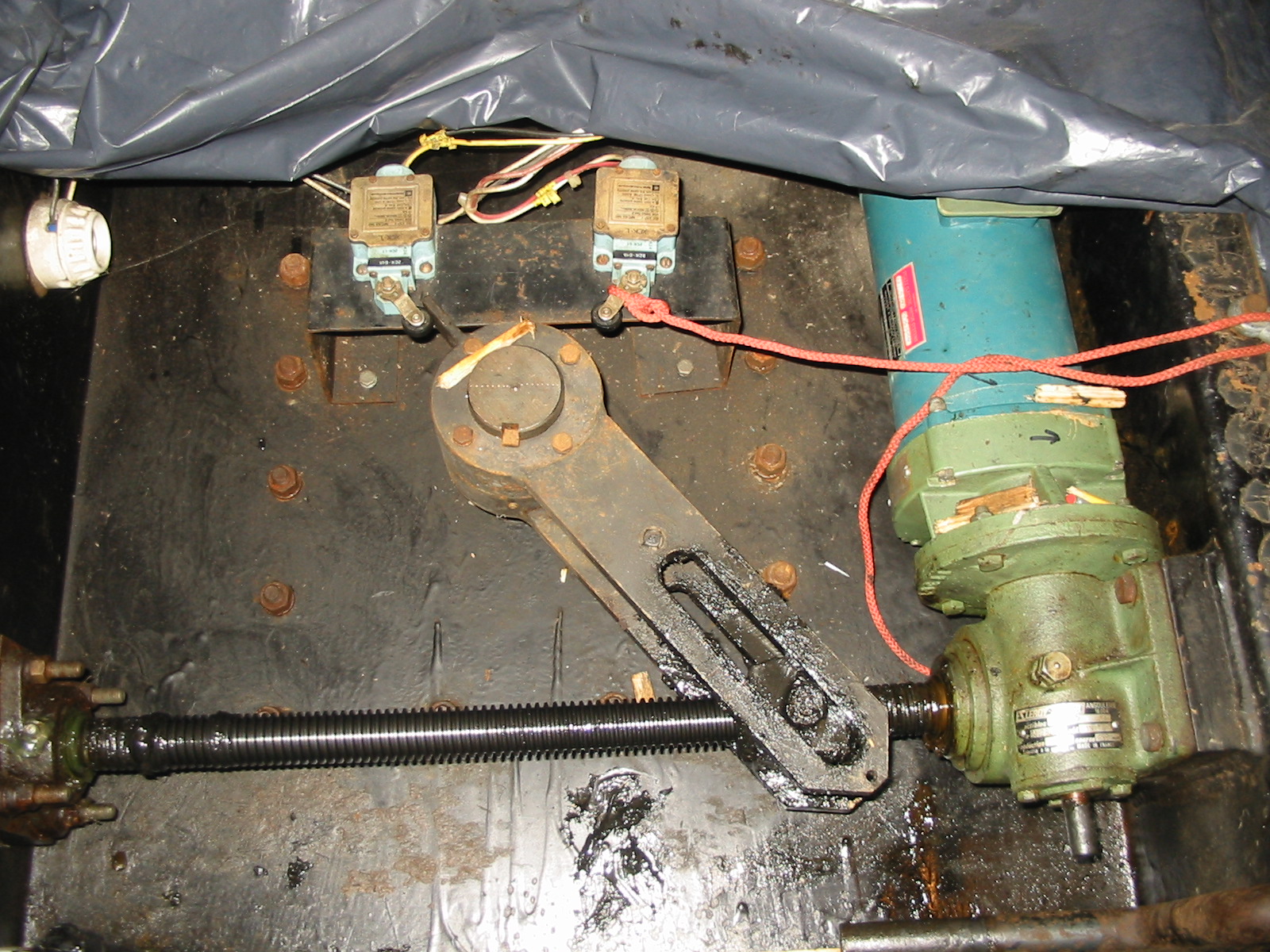
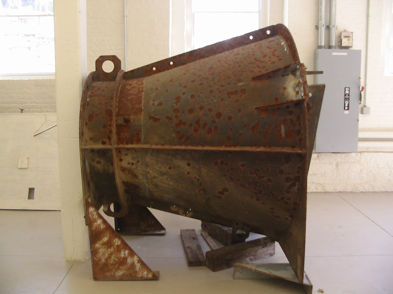
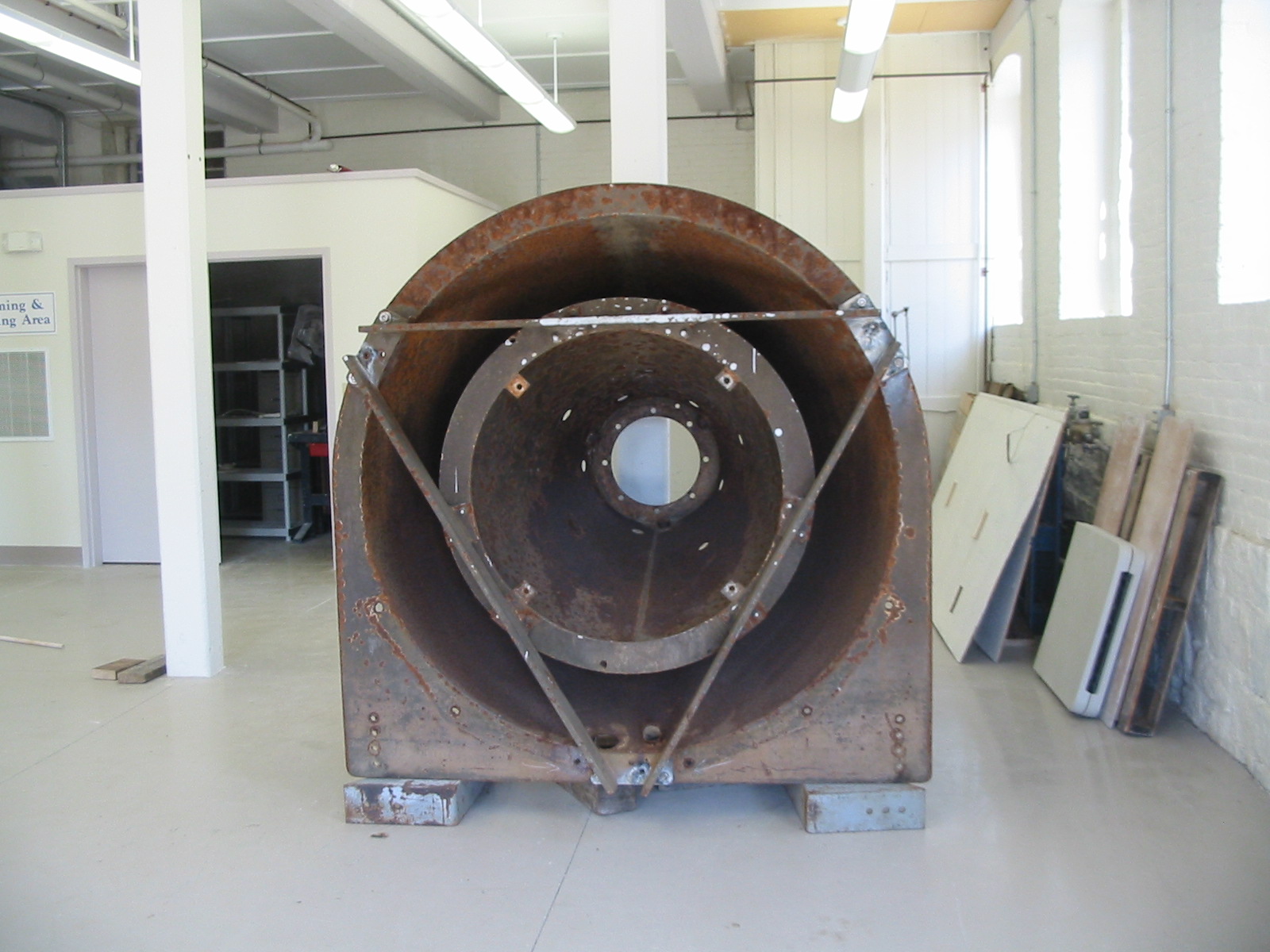
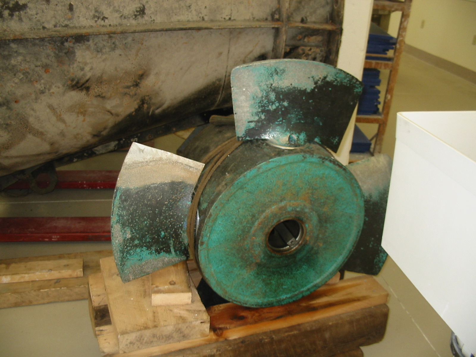
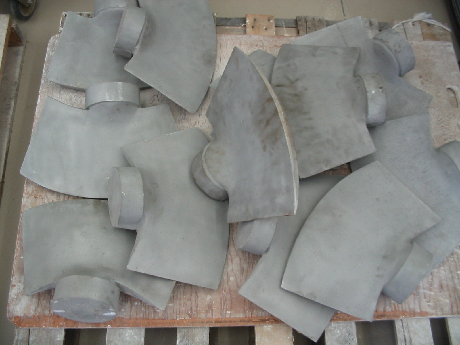
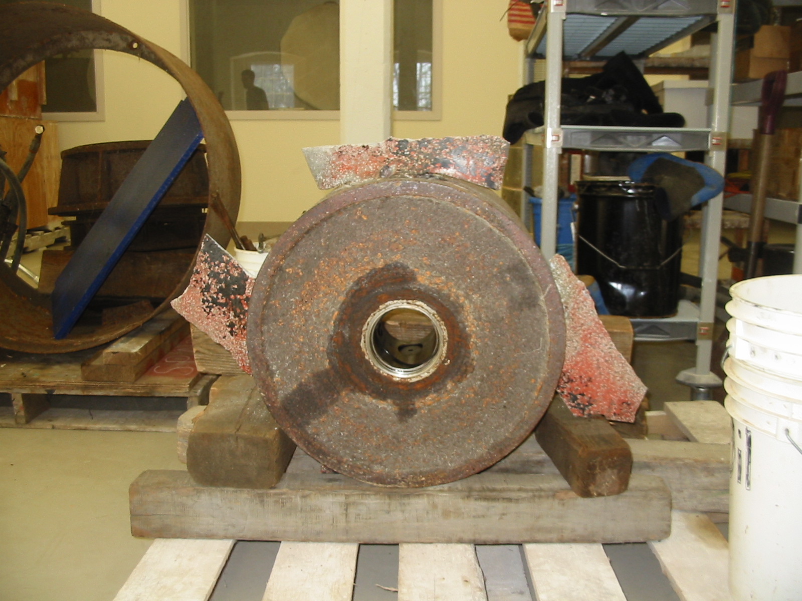
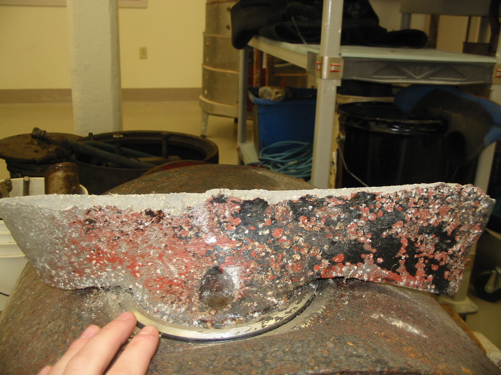
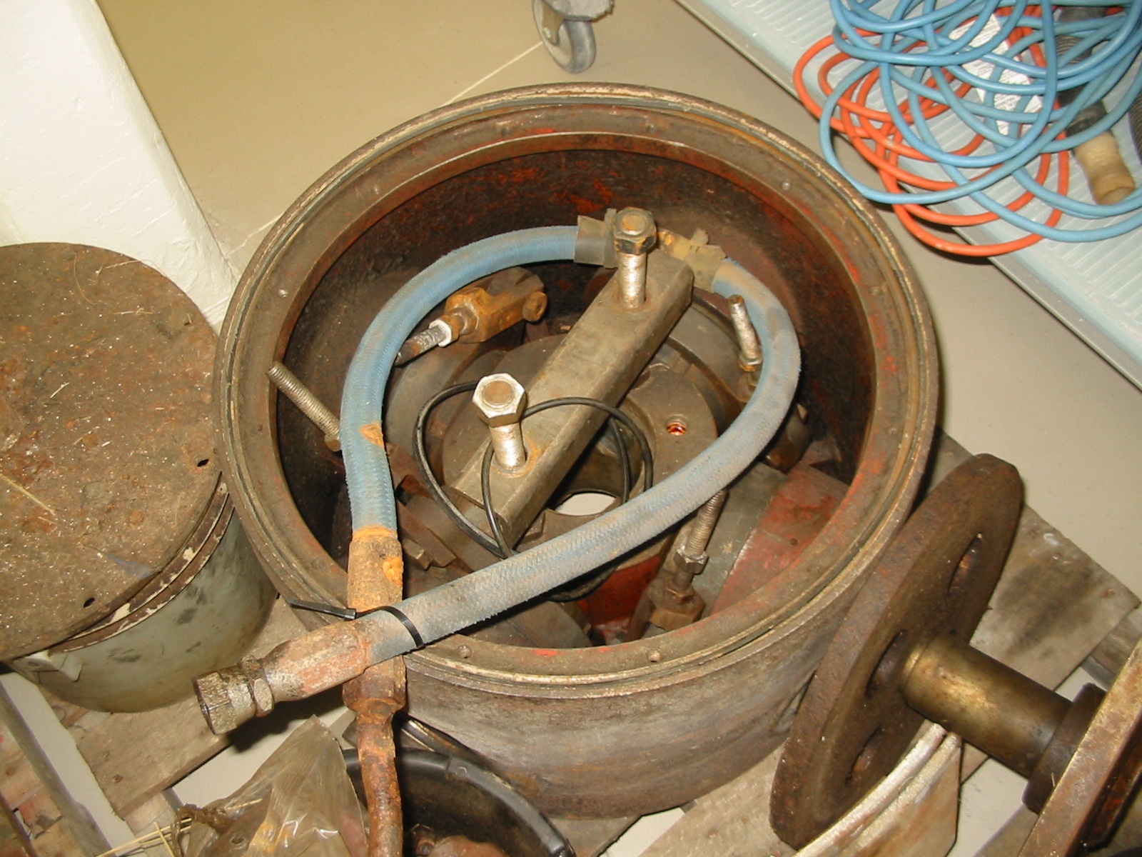
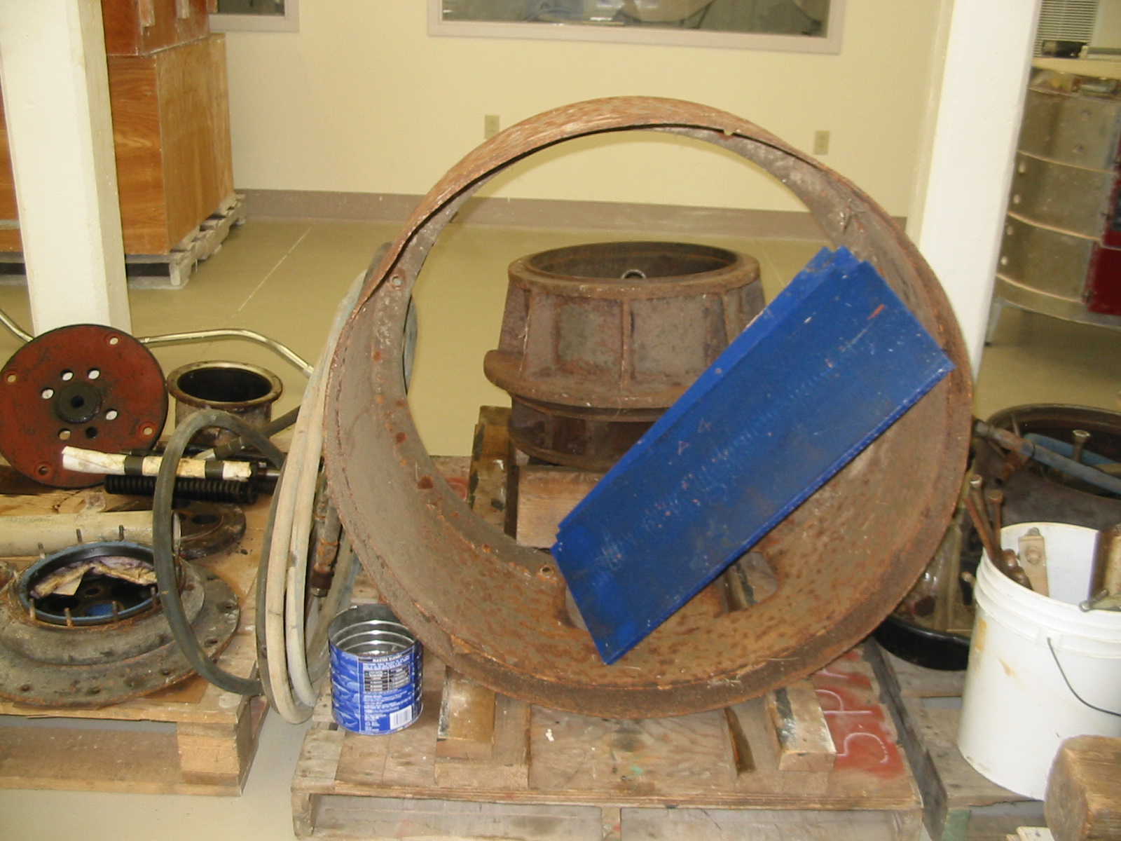
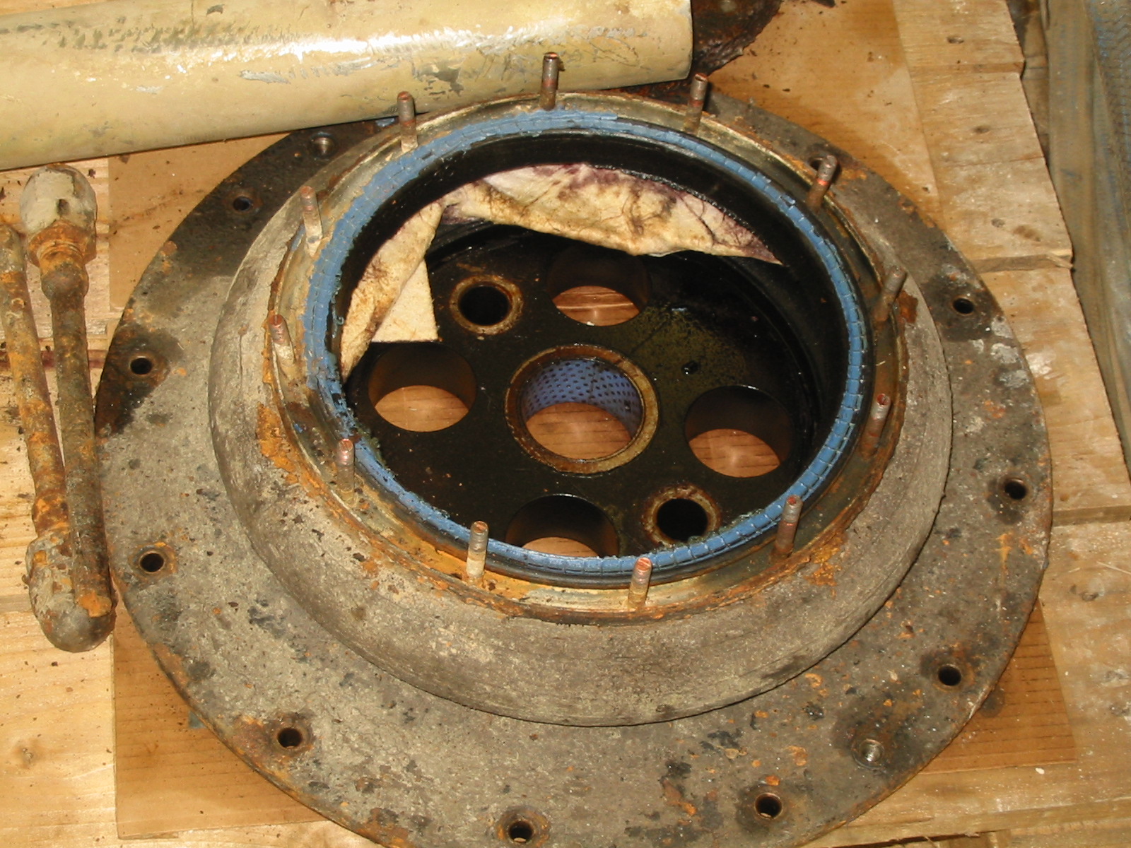
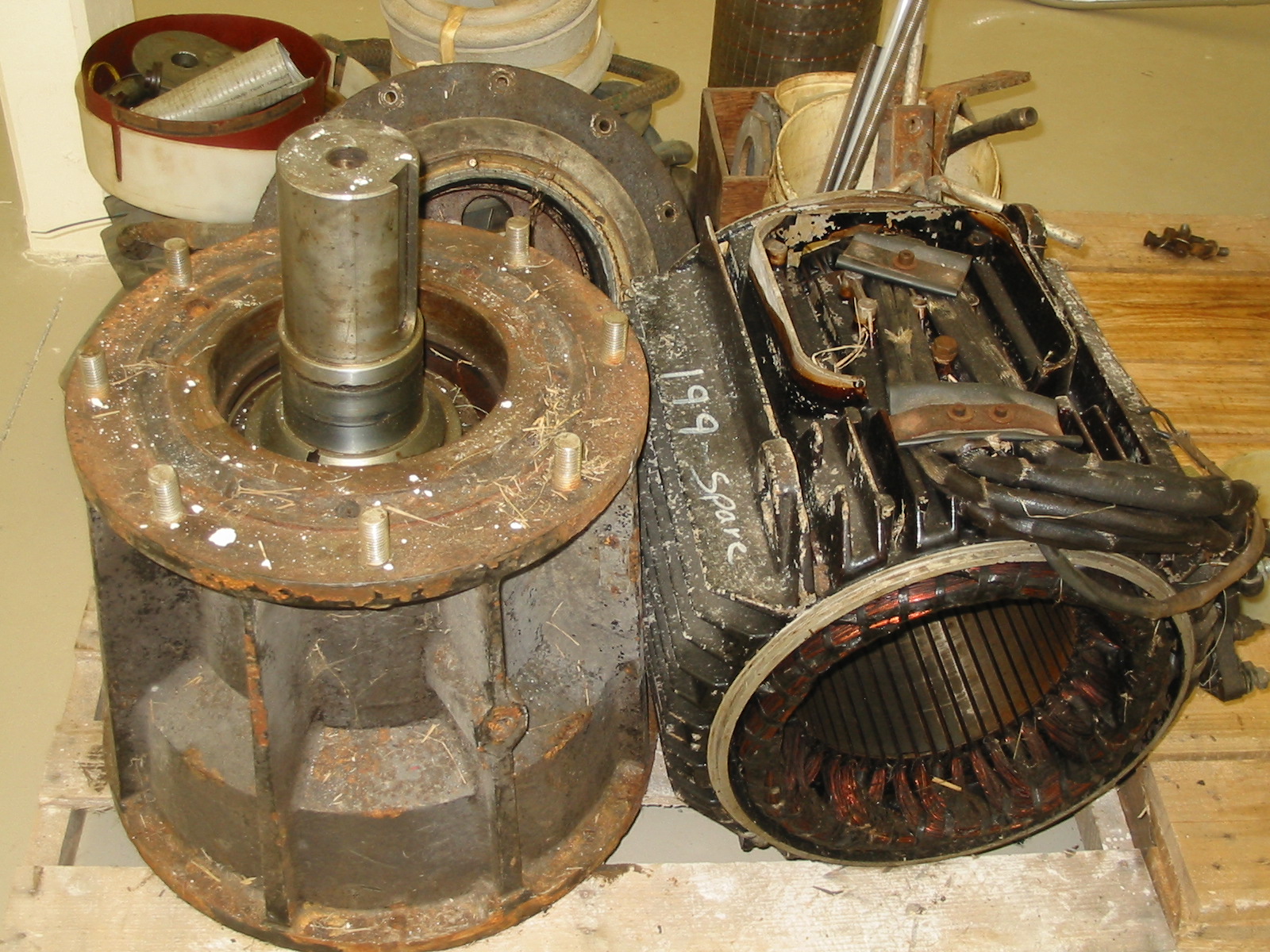
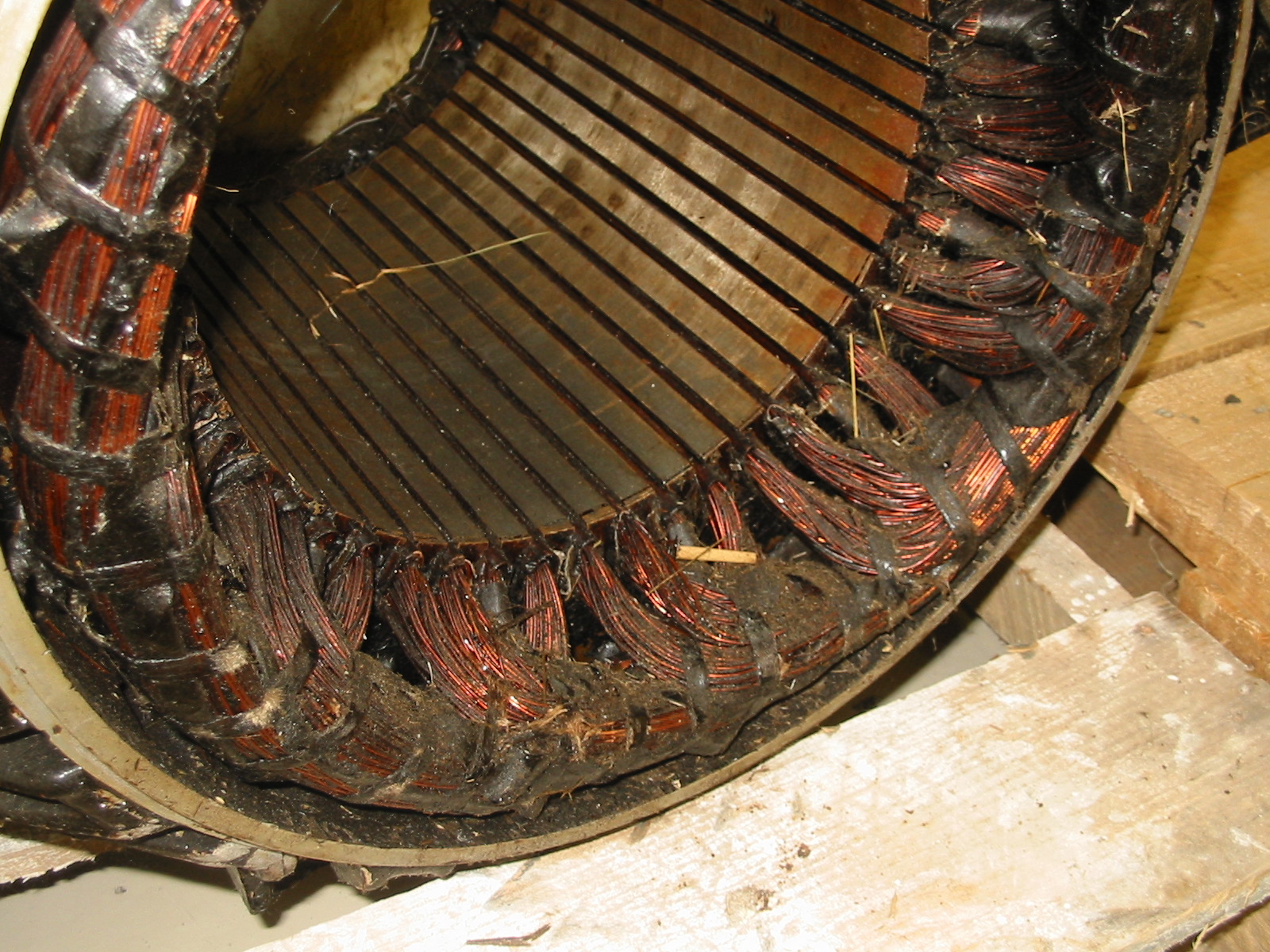
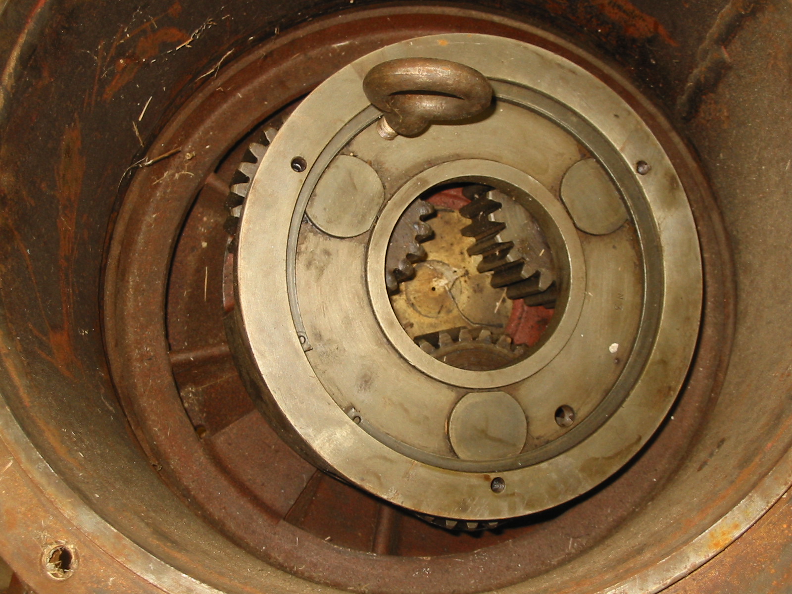
There are three Hydrolec H-9-H submersible tube turbines and generators located at Sparhawk Mills. The Hydrolec’s contain a four bladed adjustable pitch Kaplan head, connected through a planetary gearbox to an oil immersed generator. The generator is contained in a steel tank in the water flow stream. In the two automatically adjusting turbines, the blade pitch is controlled by oil pressure and a pressure actuator. The blade pitch can be changed at any time by reducing or increasing the unit’s oil pressure with a hydraulic power-pack. The manually adjustable turbine’s blade pitch can only be changed by hand. The turbine must be stopped, removed from the water, and an adjustment screw on the side adjusted. Then the turbine is re-installed.
The automatically adjusting turbines can turn down to a low flow with a higher overall efficiency curve than the manually adjustable turbine. The estimated efficiency curves are located in the appendicies. However, the automatically adjustable turbines are less reliable than then the manual adjusting turbines (the adjustable kaplan head is a complex piece of mechanical equipment).
Each turbine is rated for 90 KW at 80 cfs. The automatically adjusting turbines will turn down to a flow of 26 cfs and a production of 25 KW. It was estimated for purposes of the model that the manually adjusting turbine will turn down to 30 cfs and a production of 14 KW.
The turbine’s draft tubes are directly incorporated into the end of the tube turbines frame. The draft tubes discharge into a 70 foot long, fifteen foot wide tailrace, which discharges back into the Royal River.
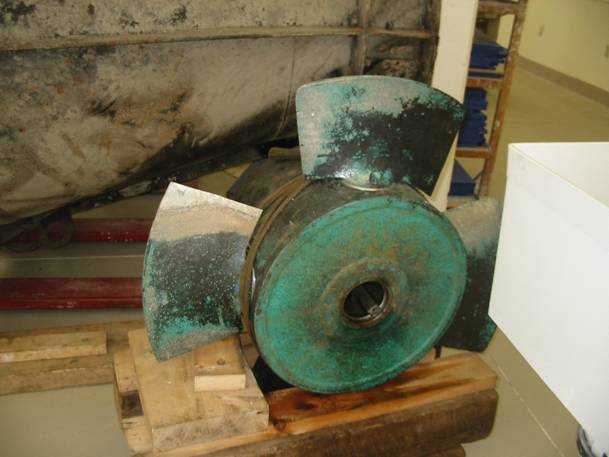
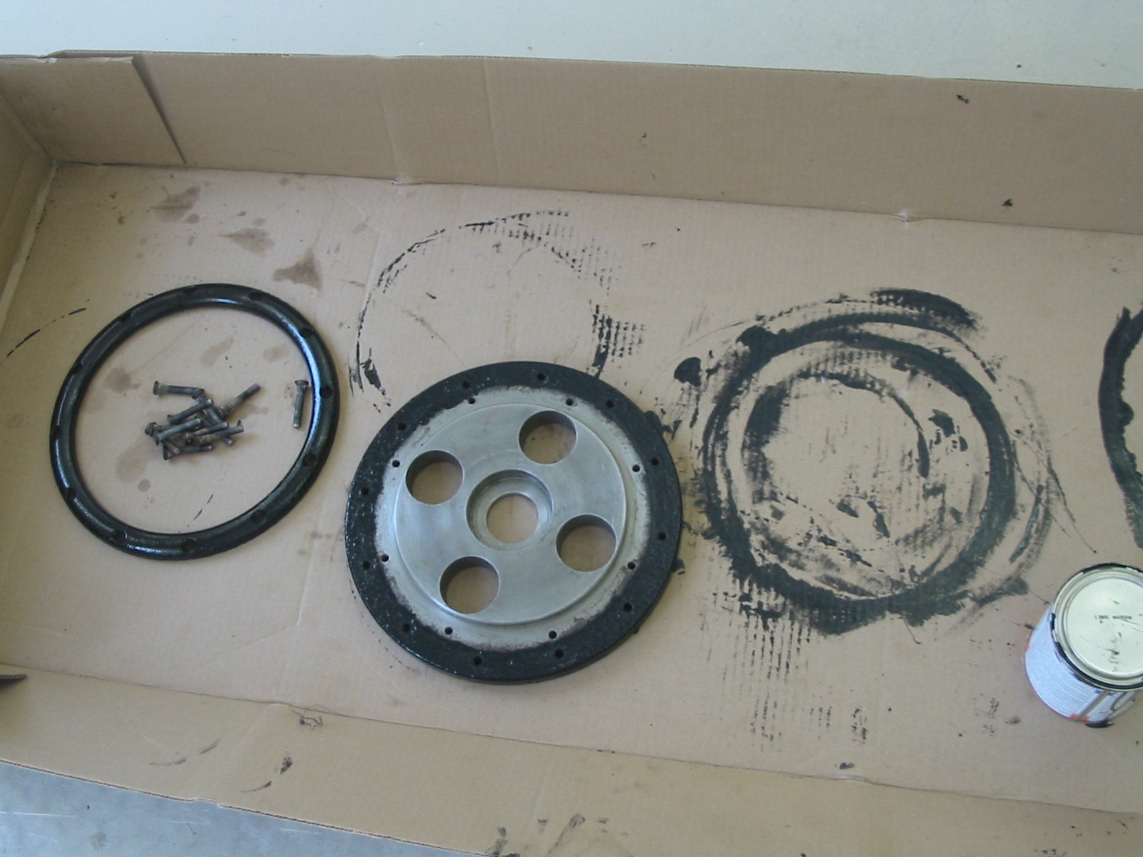
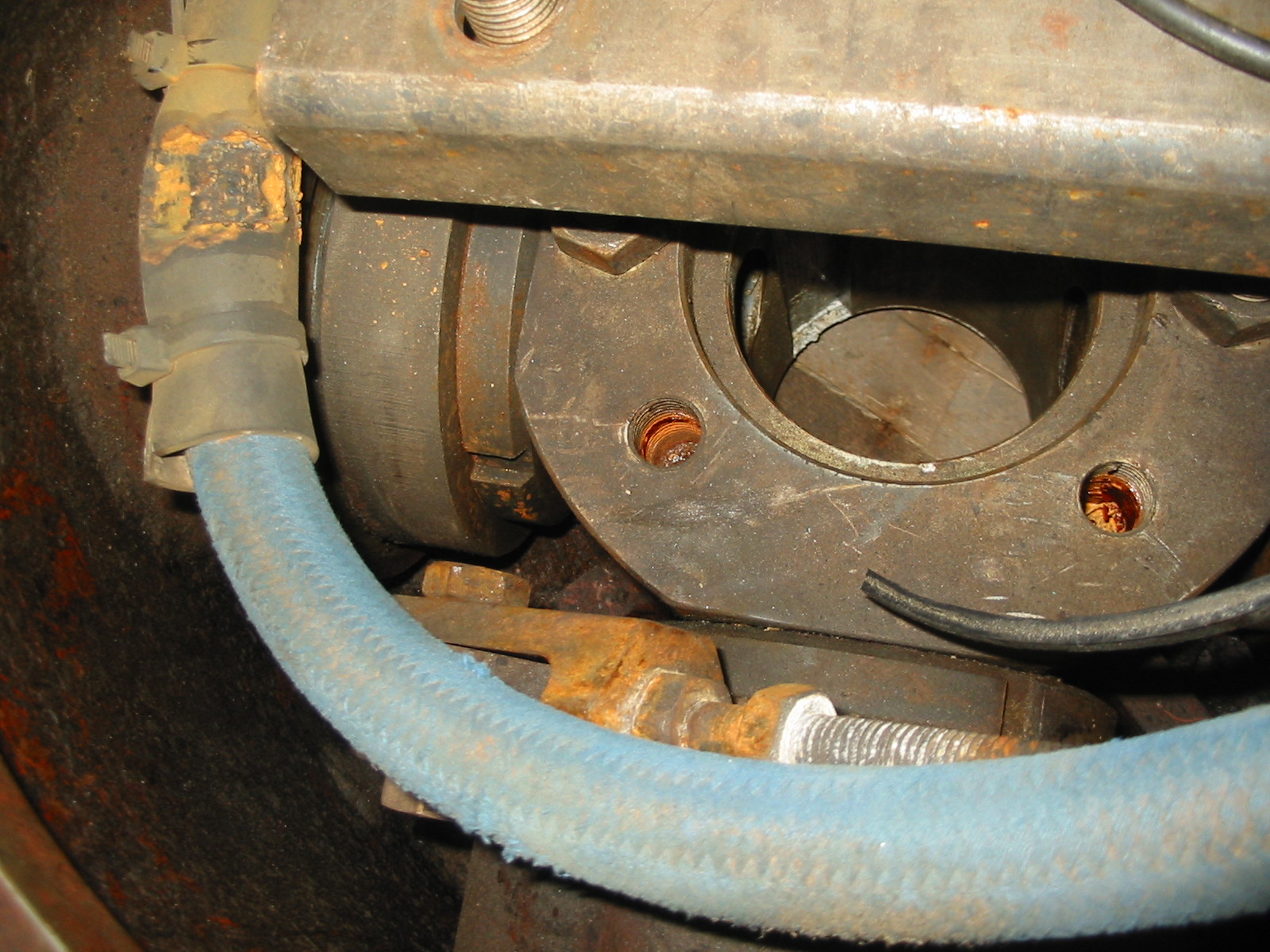
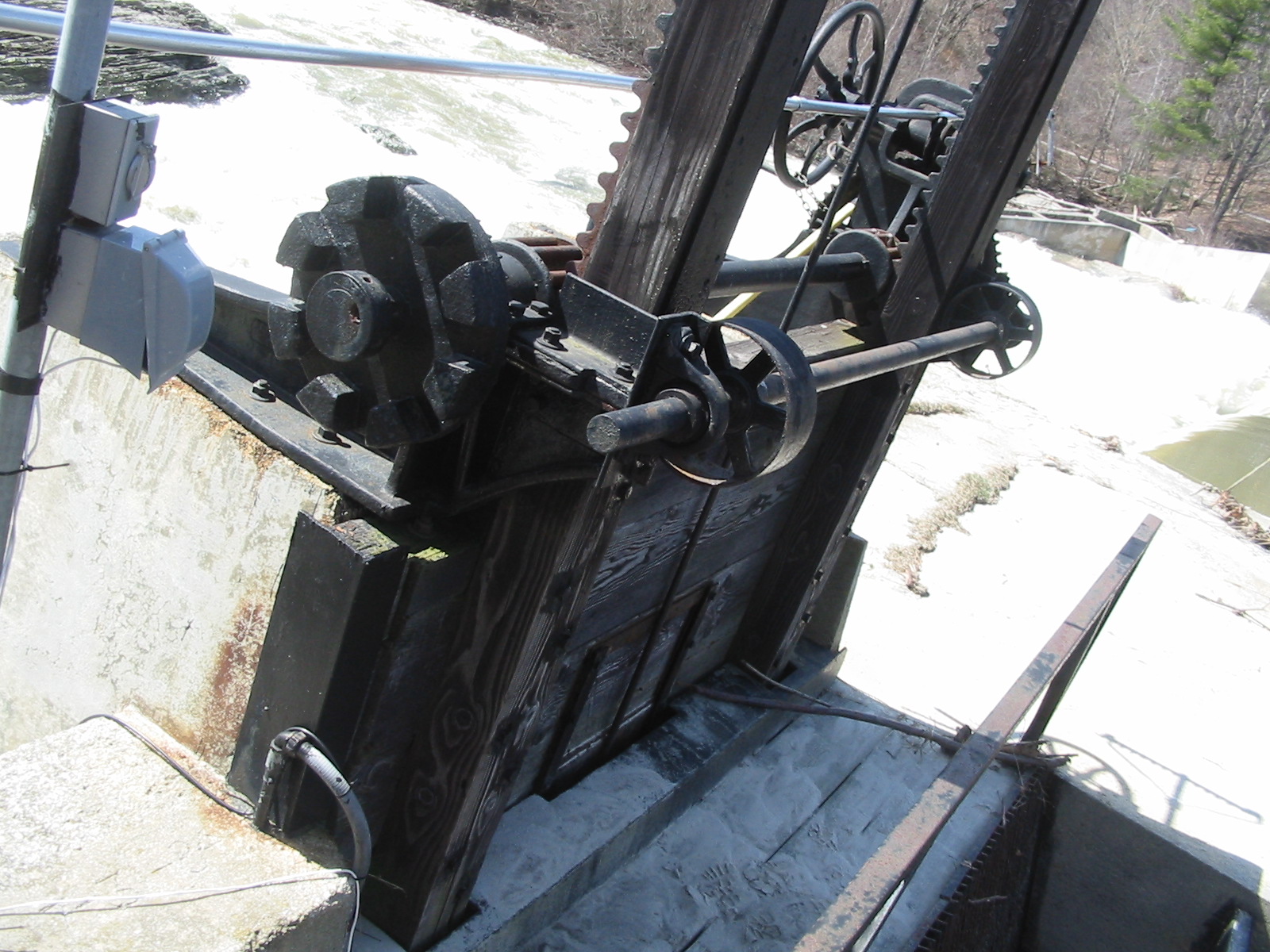
Figure 2: Automatically Adjustable Kaplan Hub
IV) Site Visit
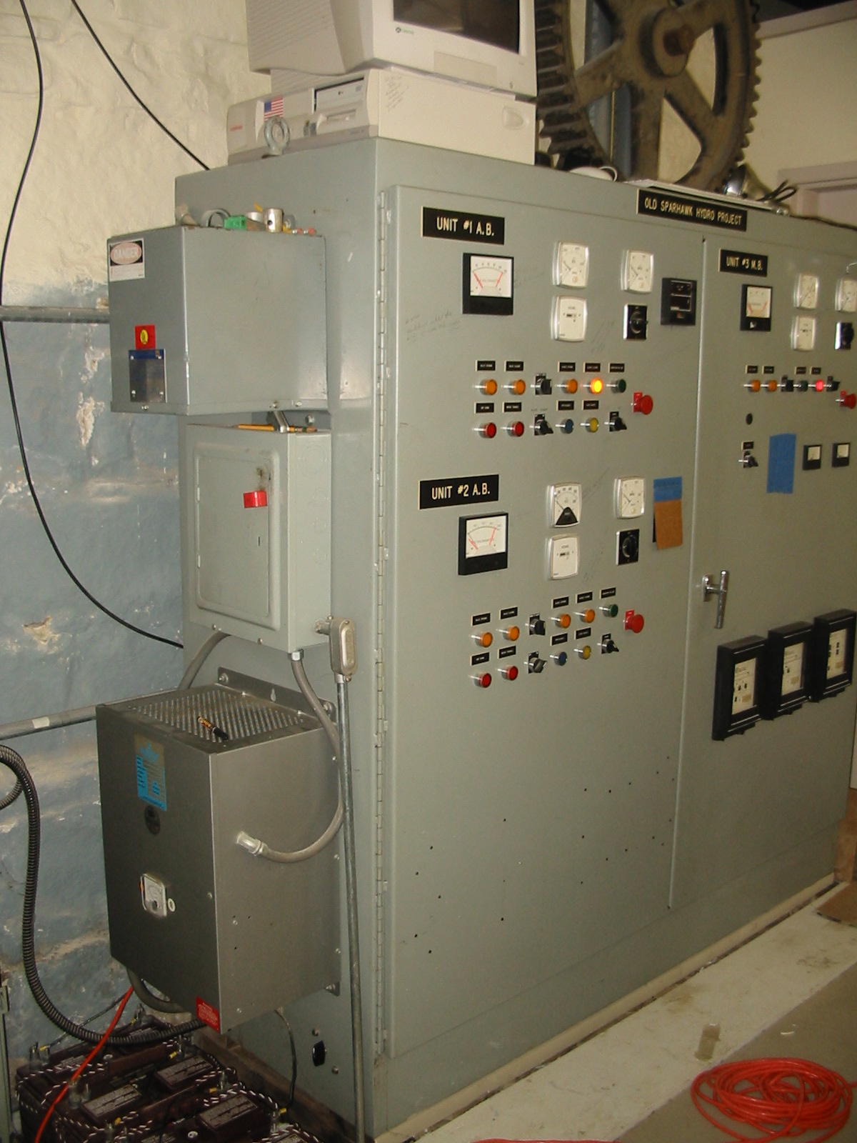
The site was visited on Saturday, April 21st, 2007. Present at the inspection were Mr. John Carroll, Ms. Celeste Fay, Bill Fay, and Will Fay of Fay Engineering Services. The weather was mild and sunny. A preliminary site tour was made. The appurtenant facilities and equipment was inspected. The dam, impoundment, shoreline, headworks, penstock, switch gear, control system, power pit, Hydrolec generating equipment, and tailrace.
The existing generating equipment, located in the room above the turbine pit was examined in detail. The owner, John Carroll was interviewed by Fay Engineering Services about the site in general and about specific issues concerning the items list above. This interview was extremely helpful in completing this report.
V) HYDROLOGY:
The drainage area of a river station is that area bounded by the drainage divide. The divide is that line which defines the direction a drop of rainwater will flow. If the drop falls on one side of the divide it flows to the river. If the drop falls on the other side it flows away from the river into the next river basin. The divide is usually the tops of the surrounding hills. Such a drainage area can be defined for the USGS gage for the Royal River at Yarmouth, Maine (141 square miles). The USGS gage is located directly downstream of the dam, with no contributing drainage area between the two. Therefore, the flow at the gage can be considered the flow at the dam, with no modification factors. This means there is no uncertainty about the gages correlation of flow with the flow at the dam. The drainage area of the Bridge Street Dam was also measured with a digitalized USGS Mapping program called TopoScout.

Figure Three : Drainage Area of Bridge Street Dam
Figure Four is a graph of the average river flow at Sparhawk Mills for each year of the period of record 1950 to 2003. The average flow of the Royal River for this period was 272 cfs.
Figure Four: Average Annual Flows at Sparhawk Mills
Figure Five depicts the mean monthly flows at the gauge for the period of record.
Figure Five: Average Monthly Flows at Sparhawk Mills
Figures Six and Seven demonstrate the minimum and maximum extremes at Stevens Pond for each year of the period of record.
Figure Six: Minimum Annual Flows
Figure Seven: Maximum Annual Flows
Figure Eight is a flow duration curve for Sparhawk Mills.
Figure Eight: Flow Duration Curve
II) MODEL METHODOLOGY:
The model was prepared on an Excel spreadsheet, which was running on a Lenovo notebook. The notebook's memory has been expanded to 50.0 gigabytes to provide for the size of the model.
The model assumes that the USGS flow is correct and is the independent variable. It is used, unmodified from the USGS gage located below the dam. All river flows up to the hydraulic capacity of the combined turbines was assumed to flow through the turbines without an increase in headwater. For flows greater then the station capacity, the weir equation was back solved for the rise in headwater elevation. During the interview the owner stated that the power plant had a head that ranged from 18 to 21 feet. A table of the total head acting on the turbines for different river flows was linearly extrapolated from the above stated head conditions. This was done for all recorded river flows at the project.
Since no efficiency curve values are available and none were given by the Leroy-Somners Company for their Hydrolec turbines, efficiency curves had to be estimated from actual records and professional judgment. The hydropower plant at Golden Pond, in Ashland, New Hampshire, has one automatically adjustable Hydrolec H-9-H on 18 feet of head. There is also six years of production data available for the site and the Hydrolec turbine. If one, is to take the best month of production from the records and compare it to the theoretical amount of power the turbine could produce in one month. You get a calculated efficiency of 75 percent. Fay Engineering has documents on the Leroy-Somners, Hydrolec turbine for Golden Pond Hydro. In that literature, a 70 percent efficiency rating is given for a Hydrolec H-9-H. The rest of the rating curve was extrapolated from a peak efficiency of 75 percent for an automatically adjustable turbine and 70 percent for a manually adjustable turbine.
Based on the net head and flow passing through the turbines, an excel lookup table of turbine efficiencies was entered. The daily production was then determined from the product of the flow, head, efficiencies, and 24 hours per day divided by 11.81 to get kilowatt-hours.
IX) RESULTS
The model’s estimate of the average production of Sparhawk Mills, for the period of record is 938,000 KWh/year.
X)) EQUIPMENT REHAB
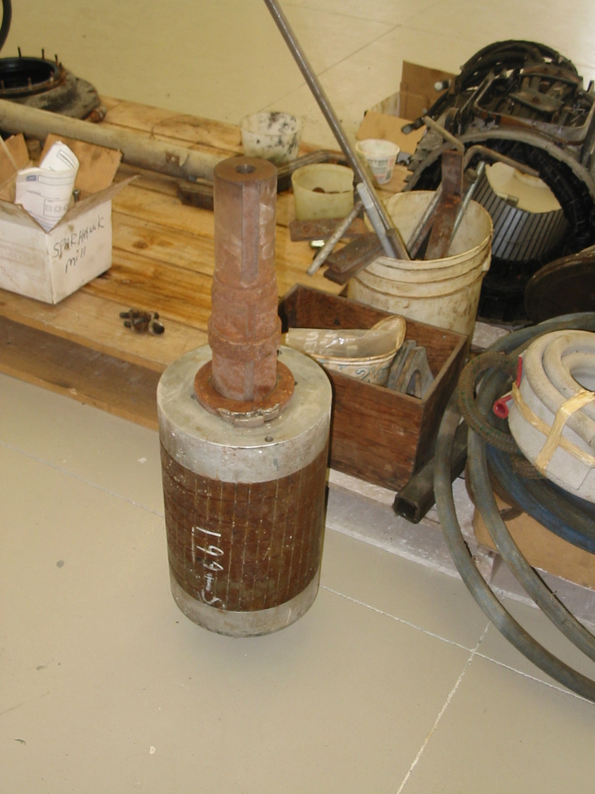
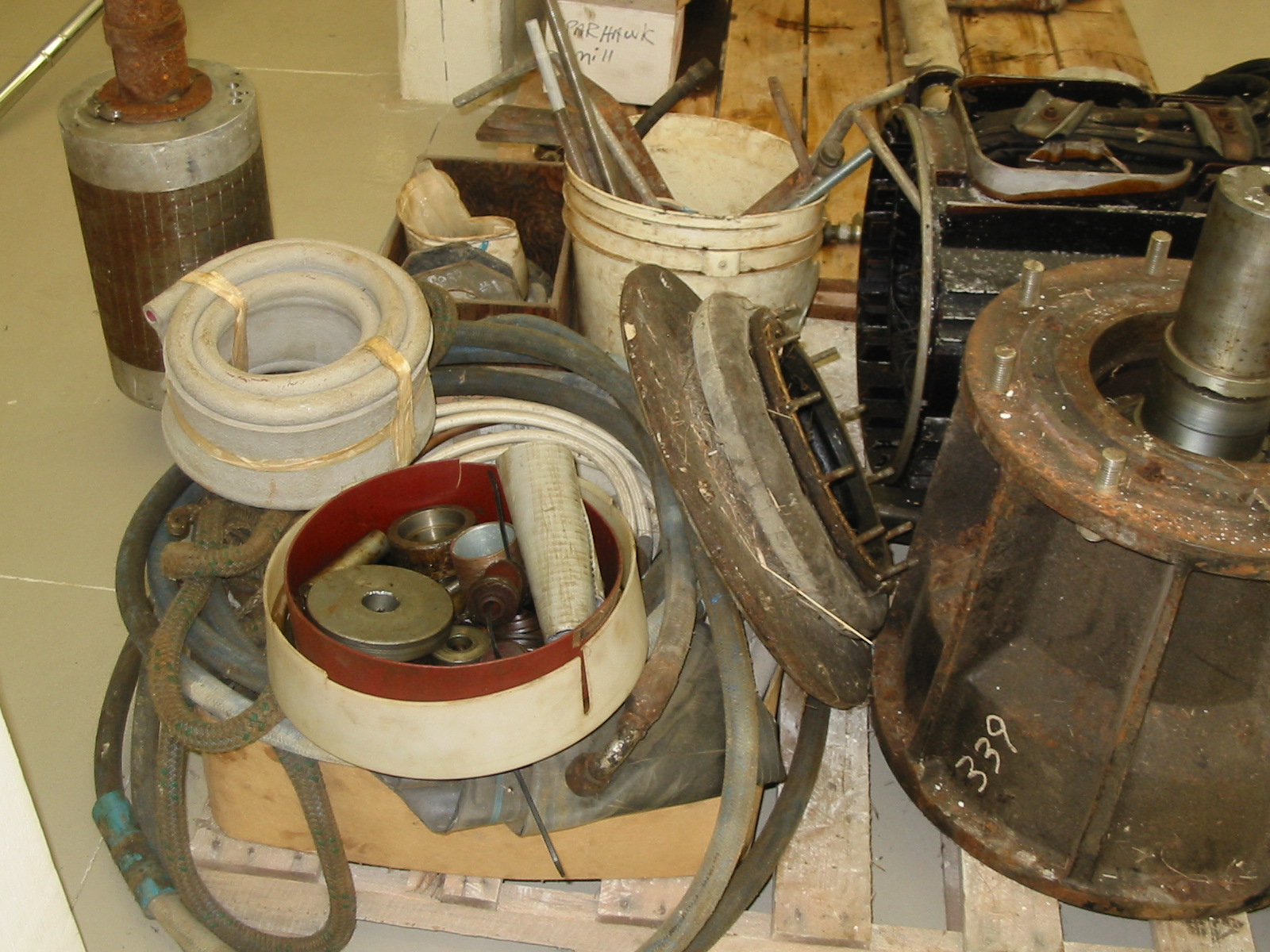
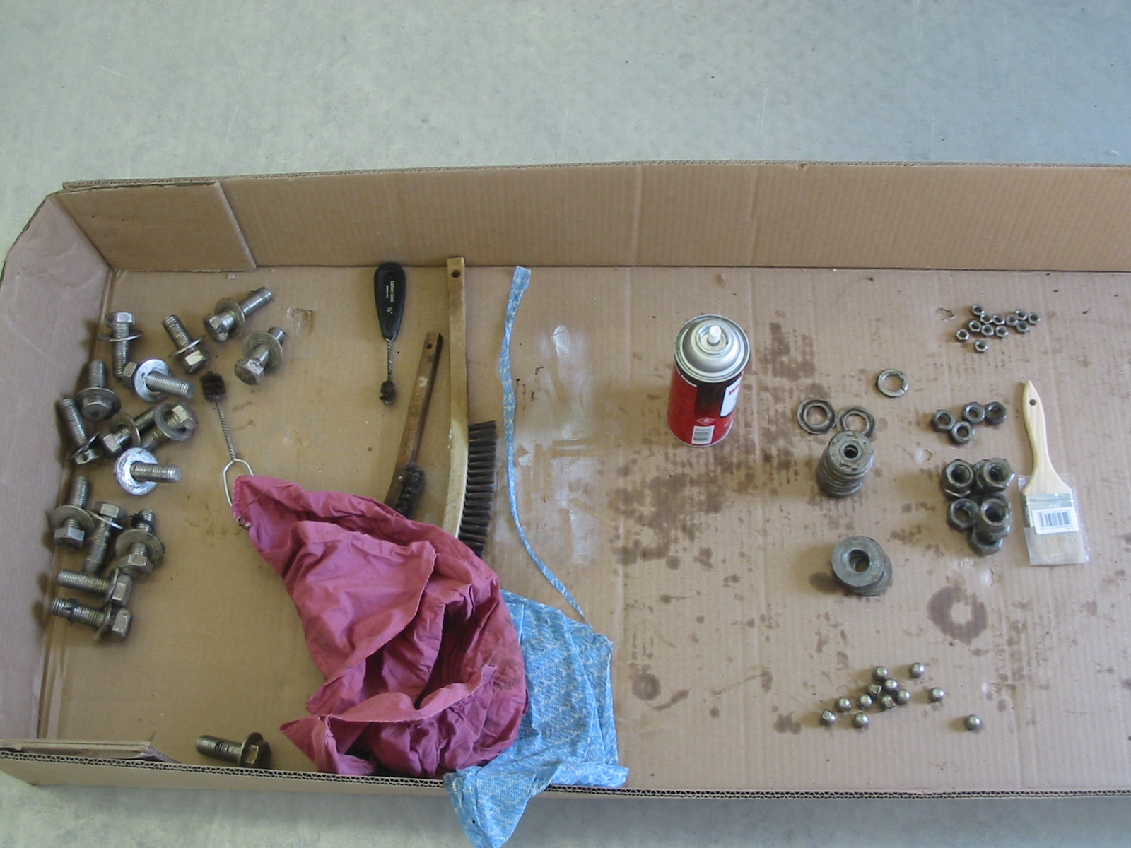
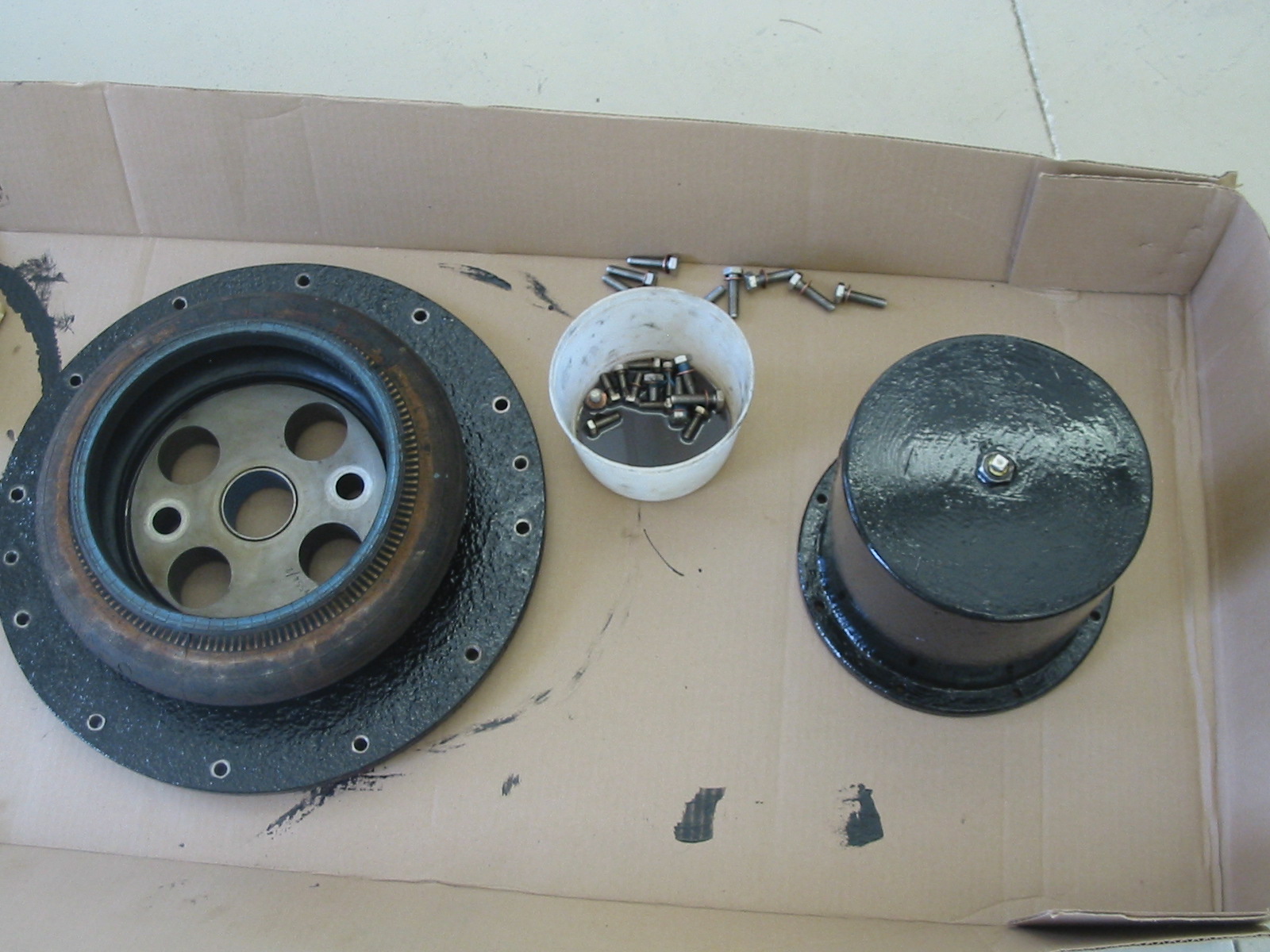
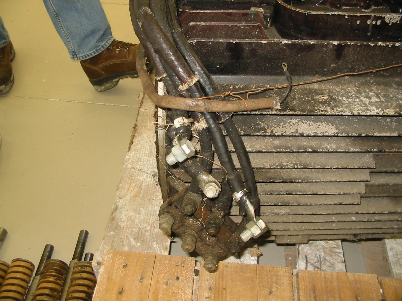
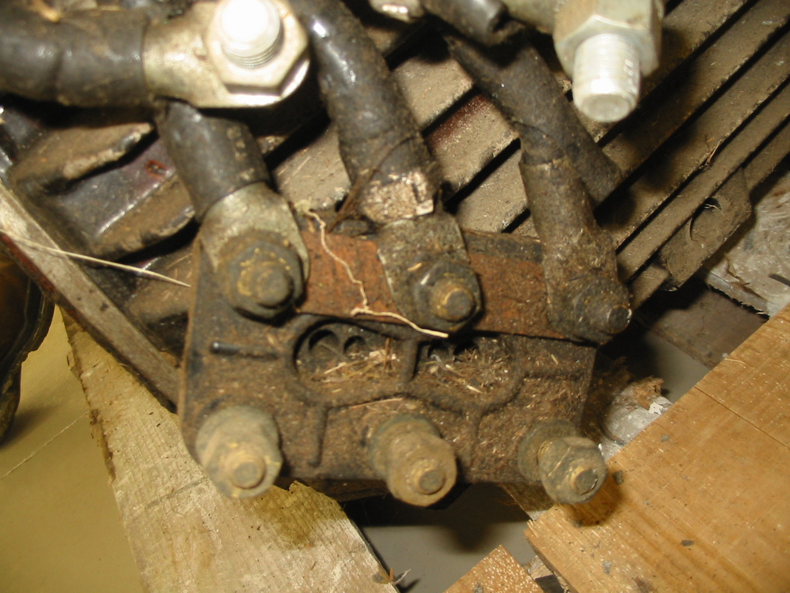
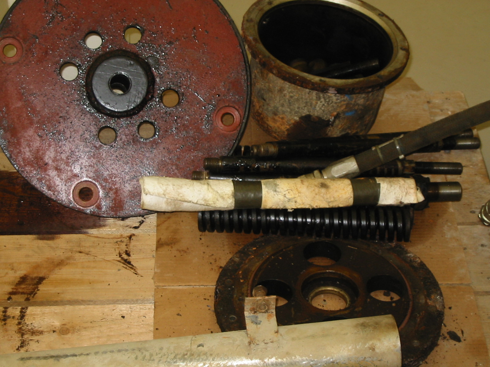
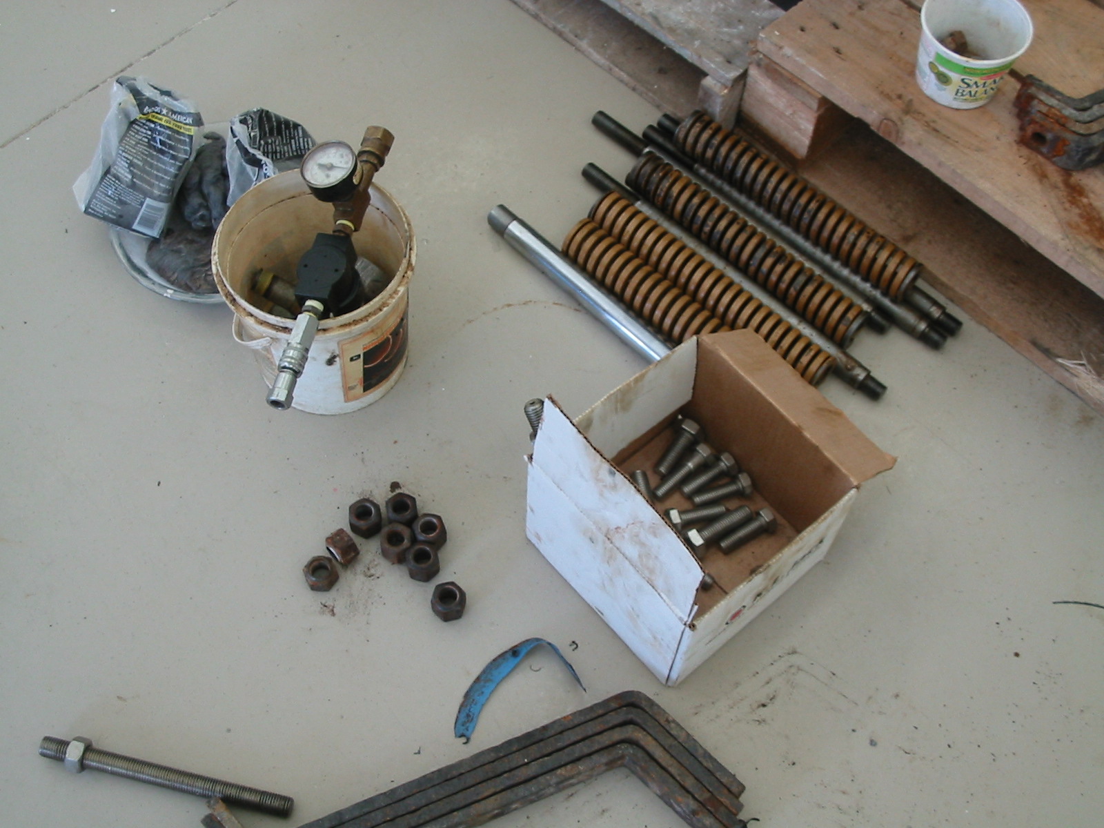
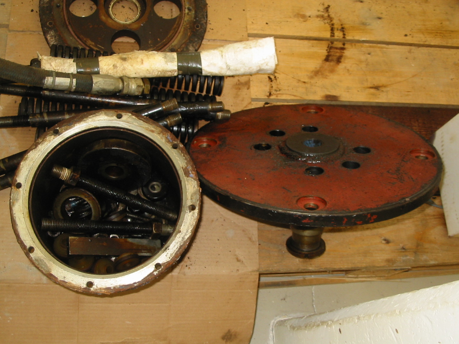
Fay Engineering Services’ experience with Hydrolec H-series machines include an H-11-H in Tannery Pond Hydro, two H-11-H’s at Old Sturbridge Village, and a H-9-H at Golden Pond Hydro. It is our experience that these machines breakdown and a give plethora of various mechanical problems. The previous owner of Golden Pond Hydro (a Hydrolec H-9-H turbine/generator installed in Ashland, New Hampshire), George Legassa, said his machine was removed nine times in thirteen years. It appears that the majority of these problems happened in the second half of the thirteen years. This indicates that the mechanical parts of the turbine-gearbox-generator wore and failed. In our financial analysis for the equipment rehab, we replaced all wearable parts including bearings, wear sleeves, bushings, airbags, etc. Also due to the environmental liability of having 60 gallons of pressurized oil in each turbine over the river, all seals should be replaced. This includes the mechanical oil seal, all o-rings, new fasteners, new top hat, new oil lines, and liberal use of silicone sealant. With parts, labor, a five percent contingency markup, and a 5 percent markup for profit, it will cost $38,139.20 per machine or $114,417.60. The itemized list of costs for the turbine rehab is located in the appendix. Also
www.frenchriverland.com can be used to see what entails a full rebuild of a Hydrolec H-9-H. A full photo documentation of a disassembly and rebuild are on the web page.
XI)) Income:
The sale of the projects renewable energy credits (REC’s) should be investigated further. The Maine Green Power Connection (MeGPC) tries to build interest in and market support for environmentally beneficial electricity products. Their website
http://www.mainegreenpower.org is a great source of green energy information in Maine. http://www.lowimpacthydro.org is the website of The Low Impact Hydropower Institute. LIHI is a non-profit organization dedicated to reducing the impacts of hydropower generation through the certification of environmentally responsible, "low impact" hydropower. A low impact hydro certification from them greatly increases you REC certificates value. Also the Massachusetts Technology Collaborative has solicitations out for funding renewable energy projects through loans, REC purchases grant money, and matching grant money. The Collaborative’s website is http://www.masstech.org/. The Rhode Island PUC is also buying REC’s. Their website on unsolicited proposals is http://www.riseo.state.ri.us/riref/programs/rfp.html. Lastly many companies are buying REC’s to reduce their overall emissions of greenhouse gasses. It might be possible to find a company interested in buying your REC’s. The price of REC’s range from $0.005/KWh to $0.05/KWh. Also, grant money from the Rhode Island PUC and the Massachusetts Technology Collaborative may be available to repair or replace the turbine-generating equipment. An unsolicited proposal is your best option to follow with grant money for equipment.Since Sparhawk Hydro does not have a purchase and sales agreement, it will be selling the power not offset on site at dump rates to the Independent Service Operator (ISO-NE). The average ISO dump power rate for the Maine Power Group over the last four years has been $0.05588/KWh. If no electrical usage was offset at the mill, the 938,000 KWh/year production would make $52,400 per year from electrical generation based on the four year ISO average.
If a $0.025/KWh REC contract was obtained an average of $23,400/year would be made from the sale of REC’s. This is a total plant income of $ 75,850/year.
Appendices
Appendix #1: Efficency Values- Automatically adjusting
Appendix #2: Efficency Values- manually adjusting
Appendix #3: Turbine-Generating Set Rebuild Price Quote
Appendix #4: ISO-NE, Maine grid, Average Dump Power Rate
Appendix 1: Automaticlly Adjusting Turbine Efficiency Values
| % Gate | Flow | efficiency |
0.59 |
47 |
0.6 |
|
0 |
0 |
0 |
0.6 |
48 |
0.6 |
|
0.2 |
16 |
0 |
0.61 |
49 |
0.6 |
|
0.21 |
17 |
0 |
0.62 |
50 |
0.6 |
|
0.22 |
18 |
0 |
0.63 |
50 |
0.6 |
|
0.23 |
18 |
0 |
0.64 |
51 |
0.6 |
|
0.24 |
19 |
0 |
0.65 |
52 |
0.6 |
|
0.25 |
20 |
0 |
0.66 |
53 |
0.67 |
|
0.26 |
21 |
0 |
0.67 |
54 |
0.67 |
|
0.27 |
22 |
0 |
0.68 |
54 |
0.67 |
|
0.28 |
22 |
0 |
0.69 |
55 |
0.67 |
|
0.29 |
23 |
0 |
0.7 |
56 |
0.67 |
|
0.3 |
24 |
0 |
0.71 |
57 |
0.67 |
|
0.31 |
25 |
0 |
0.72 |
58 |
0.67 |
|
0.32 |
26 |
0 |
0.73 |
58 |
0.67 |
|
0.33 |
26 |
0 |
0.74 |
59 |
0.67 |
|
0.34 |
27 |
0 |
0.75 |
60 |
0.67 |
|
0.35 |
28 |
0 |
0.76 |
61 |
0.67 |
|
0.36 |
29 |
0 |
0.77 |
62 |
0.7 |
|
0.37 |
30 |
0.3 |
0.78 |
62 |
0.7 |
|
0.38 |
30 |
0.3 |
0.79 |
63 |
0.7 |
|
0.39 |
31 |
0.45 |
0.8 |
64 |
0.7 |
|
0.4 |
32 |
0.45 |
0.81 |
65 |
0.7 |
|
0.41 |
33 |
0.45 |
0.82 |
66 |
0.7 |
|
0.42 |
34 |
0.45 |
0.83 |
66 |
0.7 |
|
0.43 |
34 |
0.45 |
0.84 |
67 |
0.75 |
|
0.44 |
35 |
0.45 |
0.85 |
68 |
0.75 |
|
0.45 |
36 |
0.45 |
0.86 |
69 |
0.75 |
|
0.46 |
37 |
0.45 |
0.87 |
70 |
0.75 |
|
0.47 |
38 |
0.5 |
0.88 |
70 |
0.75 |
|
0.48 |
38 |
0.5 |
0.89 |
71 |
0.75 |
|
0.49 |
39 |
0.5 |
0.9 |
72 |
0.75 |
|
0.5 |
40 |
0.5 |
0.91 |
73 |
0.75 |
|
0.51 |
41 |
0.5 |
0.92 |
74 |
0.75 |
|
0.52 |
42 |
0.5 |
0.93 |
74 |
0.75 |
|
0.53 |
42 |
0.5 |
0.94 |
75 |
0.75 |
|
0.54 |
43 |
0.5 |
0.95 |
76 |
0.7 |
|
0.55 |
44 |
0.5 |
0.96 |
77 |
0.7 |
|
0.56 |
45 |
0.5 |
0.97 |
78 |
0.7 |
|
0.57 |
46 |
0.6 |
0.98 |
78 |
0.7 |
|
0.58 |
46 |
0.6 |
0.99 |
79 |
0.7 |
Appendix 2: Manually Adjusting Turbine Efficiency Values
| % Gate | Flow | efficiency |
0.59 |
47 |
0.55 |
|
0 |
0 |
0 |
0.6 |
48 |
0.55 |
|
0.2 |
16 |
0 |
0.61 |
49 |
0.55 |
|
0.21 |
17 |
0 |
0.62 |
50 |
0.55 |
|
0.22 |
18 |
0 |
0.63 |
50 |
0.55 |
|
0.23 |
18 |
0 |
0.64 |
51 |
0.55 |
|
0.24 |
19 |
0 |
0.65 |
52 |
0.55 |
|
0.25 |
20 |
0 |
0.66 |
53 |
0.62 |
|
0.26 |
21 |
0 |
0.67 |
54 |
0.62 |
|
0.27 |
22 |
0 |
0.68 |
54 |
0.62 |
|
0.28 |
22 |
0 |
0.69 |
55 |
0.62 |
|
0.29 |
23 |
0 |
0.7 |
56 |
0.62 |
|
0.3 |
24 |
0 |
0.71 |
57 |
0.62 |
|
0.31 |
25 |
0 |
0.72 |
58 |
0.62 |
|
0.32 |
26 |
0.25 |
0.73 |
58 |
0.62 |
|
0.33 |
26 |
0.25 |
0.74 |
59 |
0.62 |
|
0.34 |
27 |
0.25 |
0.75 |
60 |
0.62 |
|
0.35 |
28 |
0.25 |
0.76 |
61 |
0.62 |
|
0.36 |
29 |
0.25 |
0.77 |
62 |
0.65 |
|
0.37 |
30 |
0.25 |
0.78 |
62 |
0.65 |
|
0.38 |
30 |
0.25 |
0.79 |
63 |
0.65 |
|
0.39 |
31 |
0.4 |
0.8 |
64 |
0.65 |
|
0.4 |
32 |
0.4 |
0.81 |
65 |
0.65 |
|
0.41 |
33 |
0.4 |
0.82 |
66 |
0.65 |
|
0.42 |
34 |
0.4 |
0.83 |
66 |
0.65 |
|
0.43 |
34 |
0.4 |
0.84 |
67 |
0.7 |
|
0.44 |
35 |
0.4 |
0.85 |
68 |
0.7 |
|
0.45 |
36 |
0.4 |
0.86 |
69 |
0.7 |
|
0.46 |
37 |
0.4 |
0.87 |
70 |
0.7 |
|
0.47 |
38 |
0.45 |
0.88 |
70 |
0.7 |
|
0.48 |
38 |
0.45 |
0.89 |
71 |
0.7 |
|
0.49 |
39 |
0.45 |
0.9 |
72 |
0.7 |
|
0.5 |
40 |
0.45 |
0.91 |
73 |
0.7 |
|
0.51 |
41 |
0.45 |
0.92 |
74 |
0.7 |
|
0.52 |
42 |
0.45 |
0.93 |
74 |
0.7 |
|
0.53 |
42 |
0.45 |
0.94 |
75 |
0.7 |
|
0.54 |
43 |
0.45 |
0.95 |
76 |
0.65 |
|
0.55 |
44 |
0.45 |
0.96 |
77 |
0.65 |
|
0.56 |
45 |
0.45 |
0.97 |
78 |
0.65 |
|
0.57 |
46 |
0.55 |
0.98 |
78 |
0.65 |
|
0.58 |
46 |
0.55 |
0.99 |
79 |
0.65 |
Appendix 3: Turbine-Generator Rehab Quote
| Parts, components, and Specific Maching | |
| Item | Price |
| Steel Top Hat |
$450.00 |
| (16)-10mm ss nuts, washers and lock washers |
$20.00 |
| Large o-ring |
$15.00 |
| Firestone airbag |
$450.00 |
| (4) Tie rod flexible bushing sets |
$200.00 |
| (12) Nylon bushing nuts |
$10.00 |
| (4) New Tie rods |
$20.00 |
| Bel-crank hub cover o-ring |
$16.00 |
| (22) 12-mm ss bolt, washers |
$30.00 |
| (9) Dura-glide bushings |
$300.00 |
| (4) New ss wear sleeves |
$1,000.00 |
| (12) Stainless steel blade allen bolts |
$36.00 |
| (4) Machining Blade castings |
$1,200.00 |
| (4) Main blade o-rings |
$40.00 |
| (4) Blade trunun main o-seal |
$40.00 |
| (4) Wipers |
$20.00 |
| (4) Secondary Blade o-rings |
$10.00 |
| (4) Machine Bearing nuts set screws |
$100.00 |
| Machine keyways in belcranks and trununs |
$400.00 |
| Main shaft o-ring |
$5.00 |
| (10) tubes silicone |
$100.00 |
| New oil seal |
$3,000.00 |
| (8) 10-mm ss bolts |
$15.00 |
| Machine modification of oil seal housing |
$100.00 |
| Repair of main shaft |
$200.00 |
| Stainless Steel piping |
$200.00 |
| Large Diameter Rubber hoses with stainless steel fittings |
$600.00 |
| (8) Main support studs |
$40.00 |
| (16) nuts and lockwashers |
$20.00 |
| Generator cover o-ring |
$20.00 |
| Bolts for cover |
$50.00 |
| Generator leads o-ring |
$10.00 |
| Bolts for generator leeds |
$5.00 |
| O-ring for generator housing |
$15.00 |
| Bolts for generator housing |
$75.00 |
| (2) Generator Bearings |
$470.00 |
| Rebuild Generator |
$7,000.00 |
| (8) 20-mm nuts and studs (generator-gearbox) |
$15.00 |
| New Lugs |
$40.00 |
| Clean and Polish all gears and miscelous gear box parts |
$300.00 |
| (75) Dowell pins and machining |
$1,500.00 |
| Min shaft thrust bearing |
$600.00 |
| Main shaft radial bearing |
$300.00 |
| New main shaft Timkin Bearing nut |
$400.00 |
| (3) Spokes |
$300.00 |
| (3) acorn and (6) locking Nuts for spokes |
$85.00 |
| Rubber flexable and steel electrical conduit |
$50.00 |
| Paint and Painting Supplies |
$500.00 |
| Metal Prep (sand blasting) |
$500.00 |
| Cutting Gasses |
$200.00 |
| Belzona |
$800.00 |
| Vegitable Oil |
$2,000.00 |
| Parts and Specific Machining (Compleate Rebuild) |
$23,872.00 |
| Labor | |
| Miscelanious Machining- 40 hours at $50/hour |
$2,000.00 |
| 2 Mechanics for disassembly, reassembly, metal prep, ect.- 220 hours at $40/hour |
$8,800.00 |
| Labor Costs |
$10,800.00 |
| Subtotal Subtotal: Labor and Parts |
$34,672.00 |
| 5% Contingency |
$1,733.60 |
| 5% Profit |
$1,733.60 |
| Grand Total |
$38,139.20 |
Appendix 4: ISO Dump Market Prices 2003-2007
| Year | Month | Average Price($/KWh) |
|
2003 |
3 |
0.065 |
|
2003 |
4 |
0.042 |
|
2003 |
5 |
0.040 |
|
2003 |
6 |
0.043 |
|
2003 |
7 |
0.044 |
|
2003 |
8 |
0.040 |
|
2003 |
9 |
0.041 |
|
2003 |
10 |
0.042 |
|
2003 |
11 |
0.039 |
|
2003 |
12 |
0.046 |
|
2004 |
1 |
0.067 |
|
2004 |
2 |
0.044 |
|
2004 |
3 |
0.044 |
|
2004 |
4 |
0.046 |
|
2004 |
5 |
0.050 |
|
2004 |
6 |
0.048 |
|
2004 |
7 |
0.045 |
|
2004 |
8 |
0.042 |
|
2004 |
9 |
0.039 |
|
2004 |
10 |
0.049 |
|
2004 |
11 |
0.047 |
|
2004 |
12 |
0.054 |
|
2005 |
1 |
0.062 |
|
2005 |
2 |
0.050 |
|
2005 |
3 |
0.059 |
|
2005 |
4 |
0.056 |
|
2005 |
5 |
0.051 |
|
2005 |
6 |
0.056 |
|
2005 |
7 |
0.066 |
|
2005 |
8 |
0.081 |
|
2005 |
9 |
0.093 |
|
2005 |
10 |
0.103 |
|
2005 |
11 |
0.069 |
|
2005 |
12 |
0.095 |
|
2006 |
1 |
0.066 |
|
2006 |
2 |
0.062 |
|
2006 |
3 |
0.061 |
|
2006 |
4 |
0.060 |
|
2006 |
5 |
0.054 |
|
2006 |
6 |
0.050 |
|
2006 |
7 |
0.053 |
|
2006 |
8 |
0.062 |
|
2006 |
9 |
0.044 |
|
2006 |
10 |
0.051 |
|
2006 |
11 |
0.058 |
|
2006 |
12 |
0.053 |
|
2007 |
1 |
0.056 |
|
2007 |
2 |
0.076 |
|
2007 |
3 |
0.062 |
|
2007 |
4 |
0.064 |
'