Barrel Stave Bearing Repair Web Page
Many of the larger manufacturers of hydraulic turbines such as I.P. Morris, Newport News Shipbuilding and Wellman Seaver Morgan incorporated a barrel stave bearing to oppose the radial forces on the turbine main shaft. This bearing had long, thin, dove tailed, lignum vitae strips that were inserted in a cylindrical, cast iron housing. Once the strips were all inserted into the housing, the housing was placed on a boring mill and the wooden surfaces of the strips were bored to the diameter of the main shaft. Provisions were made to pump water between the shaft and the wood to provide lubrication. Many operators do not realize that at certain gate settings a Francis runner will create a vacuum on the crown of the runner. This sucks the water out of the lignum vitae bearing and burns the wood up. In order to provide lubrication of the wooden surface a dependable water supply must be provided.
I first ran across this type of bearing at Consolidated Edison's Red Bridge Station. It is located on the Chicopee River in Wilbraham, MA. There are two 5 megawatt S. Morgan Smith units operating on 50 feet of head. We were called in to inspect Unit One because it was making load bumping noises. We found that the main shaft was quite loose. We could not find a way to adjust the bearing. It did not have a quarter block assembly with bronze adjusting screws. We removed the stuffing box and the wet end bearing. We found a barrel stave bearing that was worn out. We also discovered a very badly worn 13 inch diameter, main shaft. We created a split metal sleeve from a piece of pipe and welded it onto the damaged shaft. We installed new lignum vitae staves and reassembled the unit.
Red Bridge's barrel stave bearing housing with the wooden staves removed.
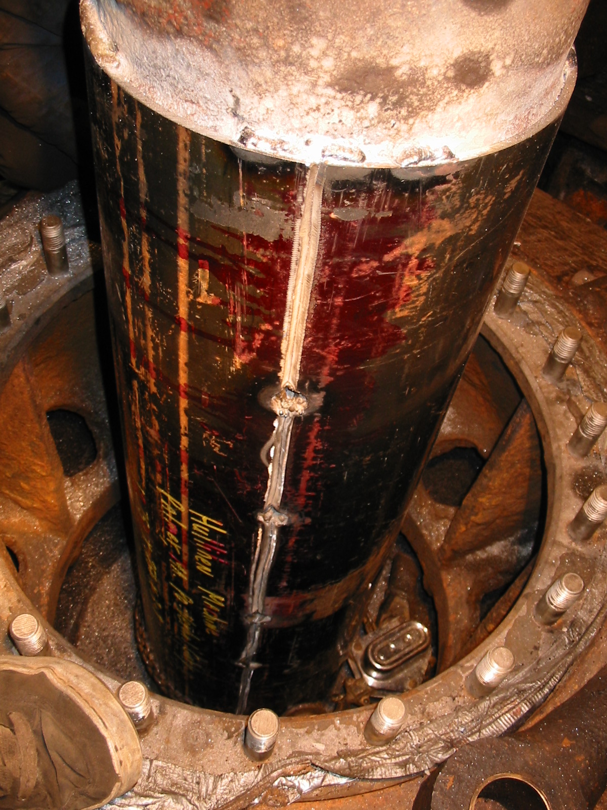
Installation of shaft sleeve at Red Bridge station
We recently had to repair the barrel stave bearing at the former Keith Paper Company in Turners Falls, MA. The following series of photos depict the process:
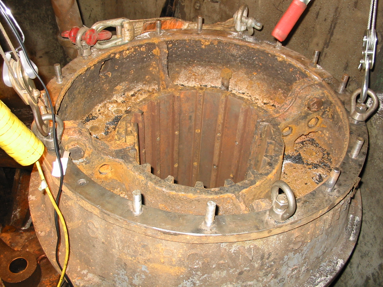
Here we have removed the stuffing box and we are looking at the top of the barrel stave bearing's housing. You can see the stuffing box gland at the top right. Notice the bell cranks that actuate the turbine wicket gates. If you look closely at the top of one of the bell cranks, you can see that it has been retro fitted with ring phetters.
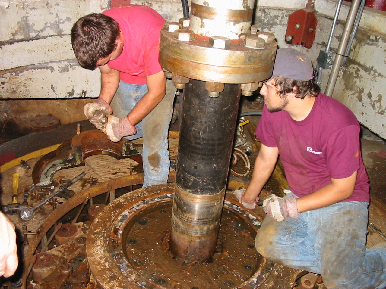
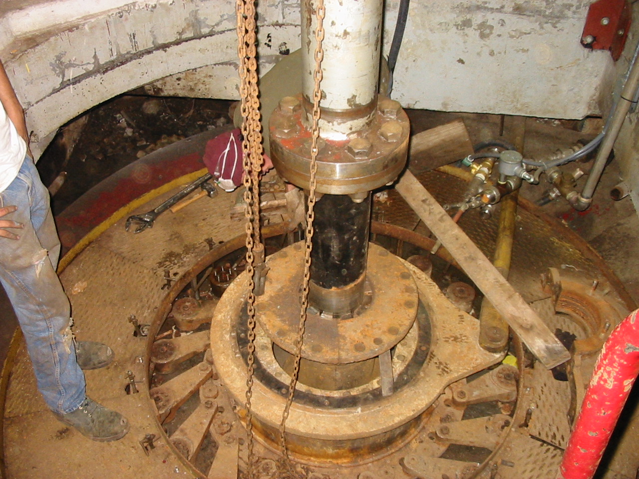
Ronnie Johnson and Cole have jacked the bearing housing out of the scroll case. They are removing the pinch bolts in order to split the bearing housing in preparation of its removal from the main turbine shaft.
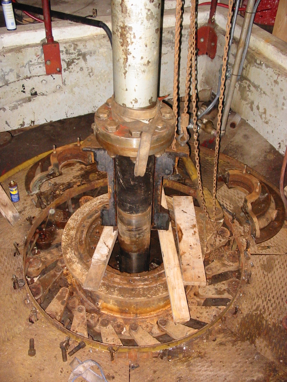
Here we have removed half of the bearing housing and we are lifting out the second half. Notice one half of the stuffing box is sitting to the right on the floor plates.
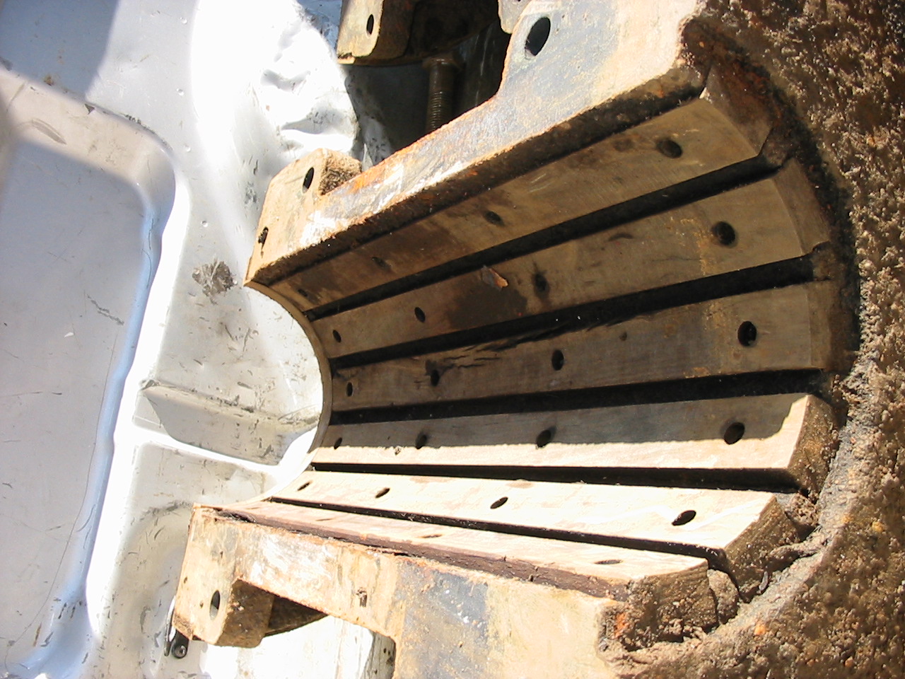
A view of the worn out bearing strips. These strips are non-adjustable. The round holes contain bronze screws that hold the strips in place. If you look closely at the top of a stripee the dove tailed shape.
Another view of the barrel stave bearing.
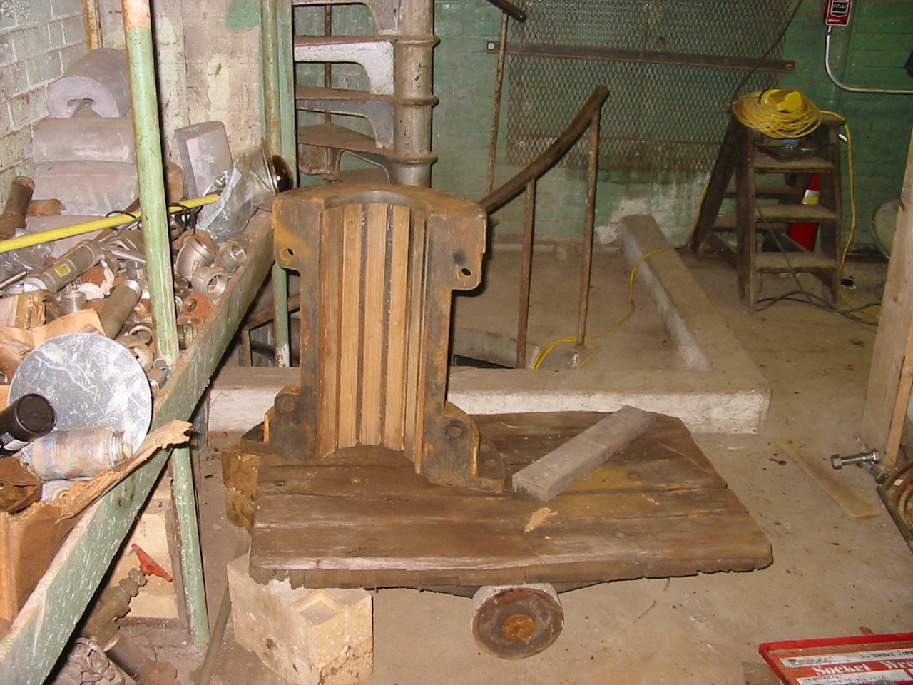
We have just lifted the completed bearing assembly onto the Bullard vertical turret lathe to be turned.
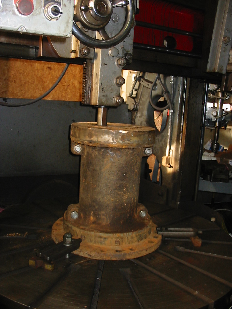
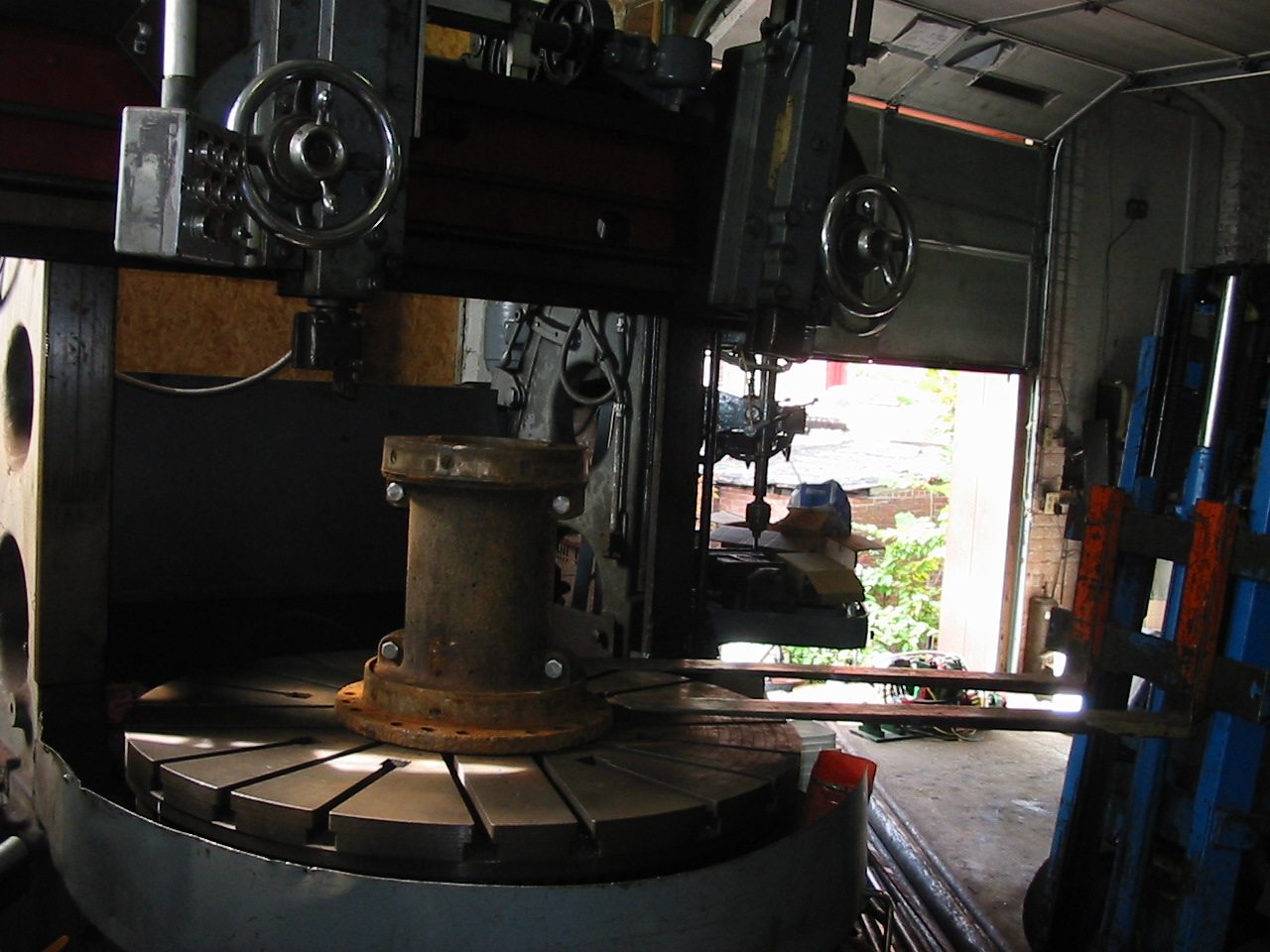
Here we have already inserted and screwed down the new strips. We have clamped the assembly onto the chuck of our 60 inch Bullard. The Wizard is about to bore the inside of the wooden strips to 8 inches internal diameter.
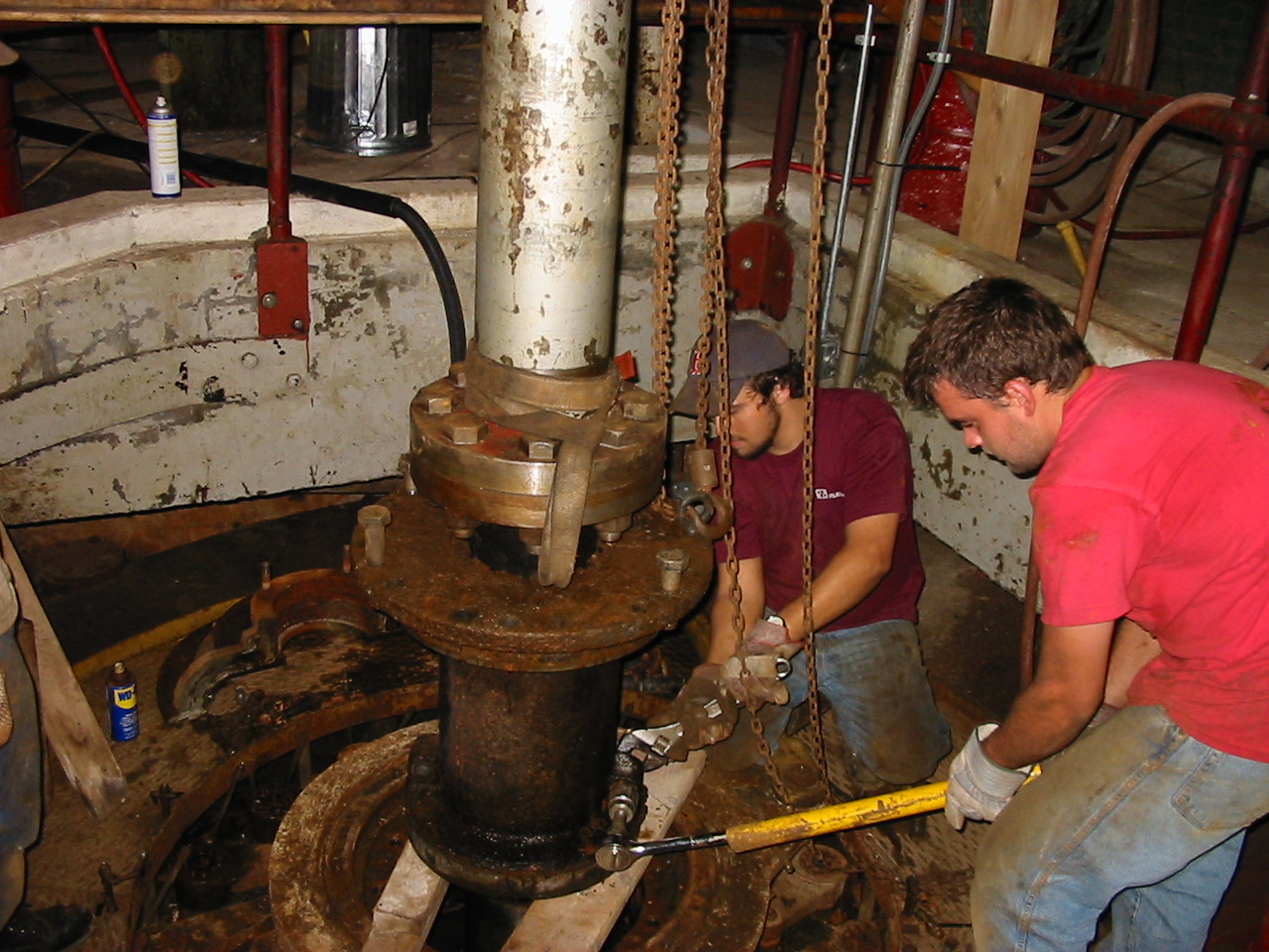
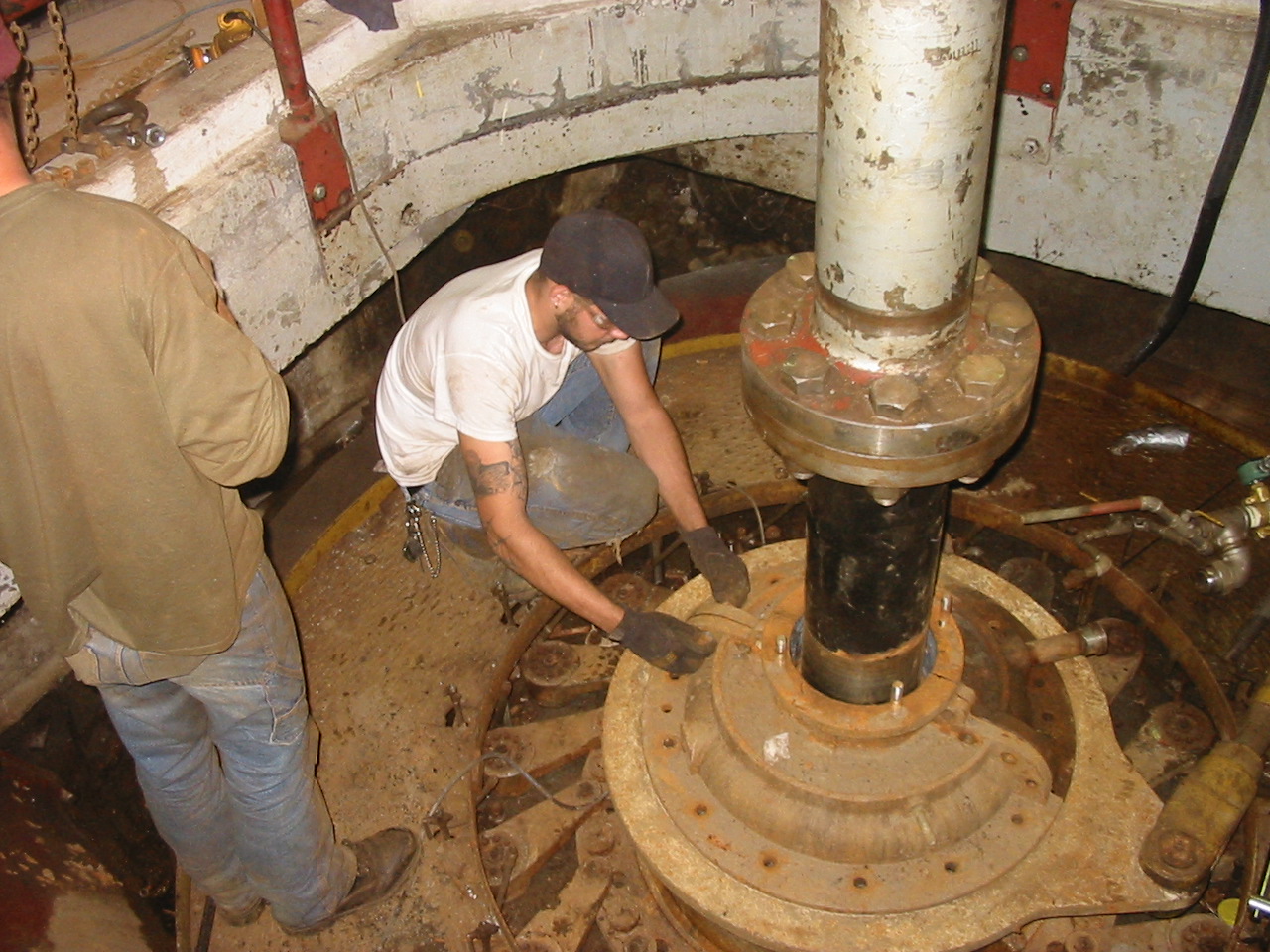
Micke Desrouche and Joe are lowering the bearing housing back into the scroll case. When we first installed the two halves of the bearing and tightened the pinch bolts the housing clamped solid to the shaft. We thought the bearing had been bored to the incorrect internal diameter. We quickly realized we were on a section of the shaft that had never been worn. We had to loosen the pinch bolts up. We were than able to lower the unit into its bore. Just as the lower set of pinch bolts were entering the scroll case, we tightened the lower pinch bolts. As we continued to lower the unit we tightened the rest of the pinch bolts.
Here Joe is installing the stuffing box. Note the 2 inch stainless steel pipe that is used to flood the bearing stave chamber.
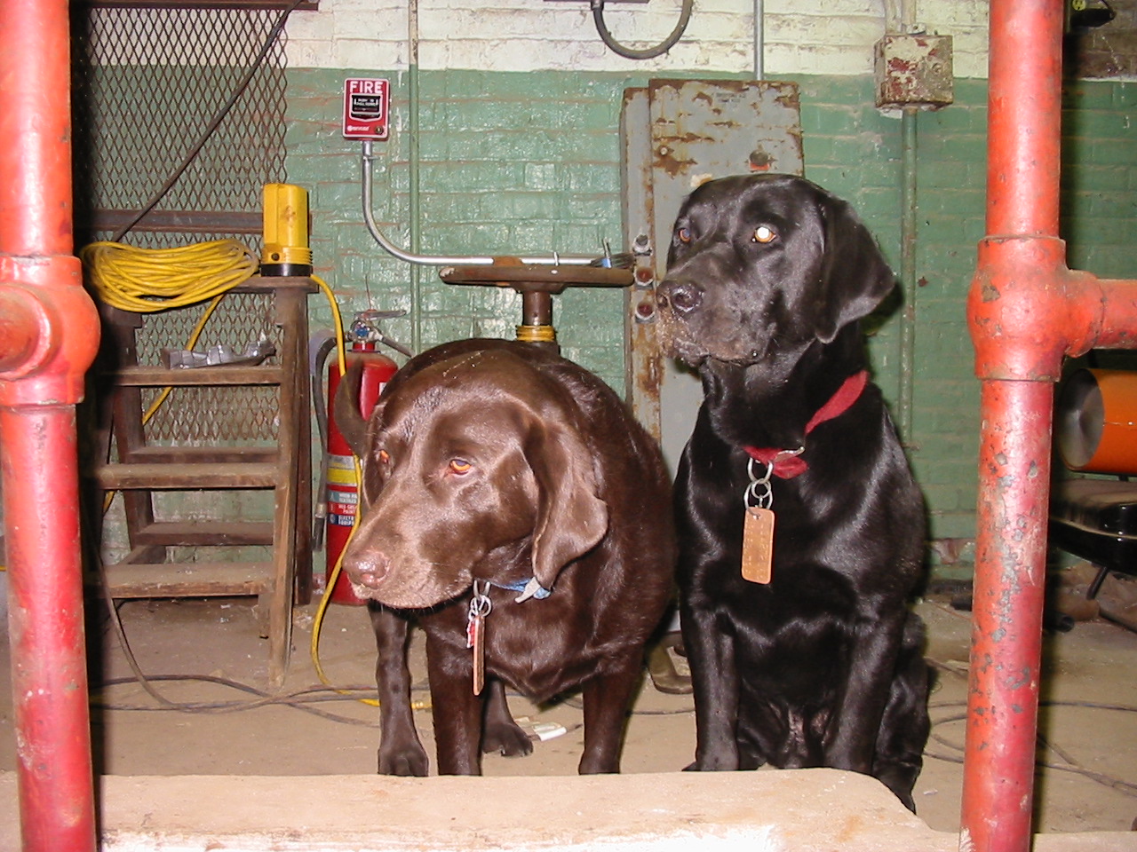
Here are our faithful supervisors. At first, they were barking out orders like a couple of dogs. By this time they were wondering when they could go home!!!