Design of Draft Tubes Page
CONICAL DRAFT TUBE COMPUTATIONS:
The simplest and most efficient, turbine draft tube is the conical shaped draft tube. It is usually vertical and is designed with a truncated cone similar to an inverted ice cream cone. Originally, turbines were designed without draft tubes. In order to work on the runner, stoplogs were inserted into the tailrace training walls and the discharge pit was pumped out.
Figure One Figure Two
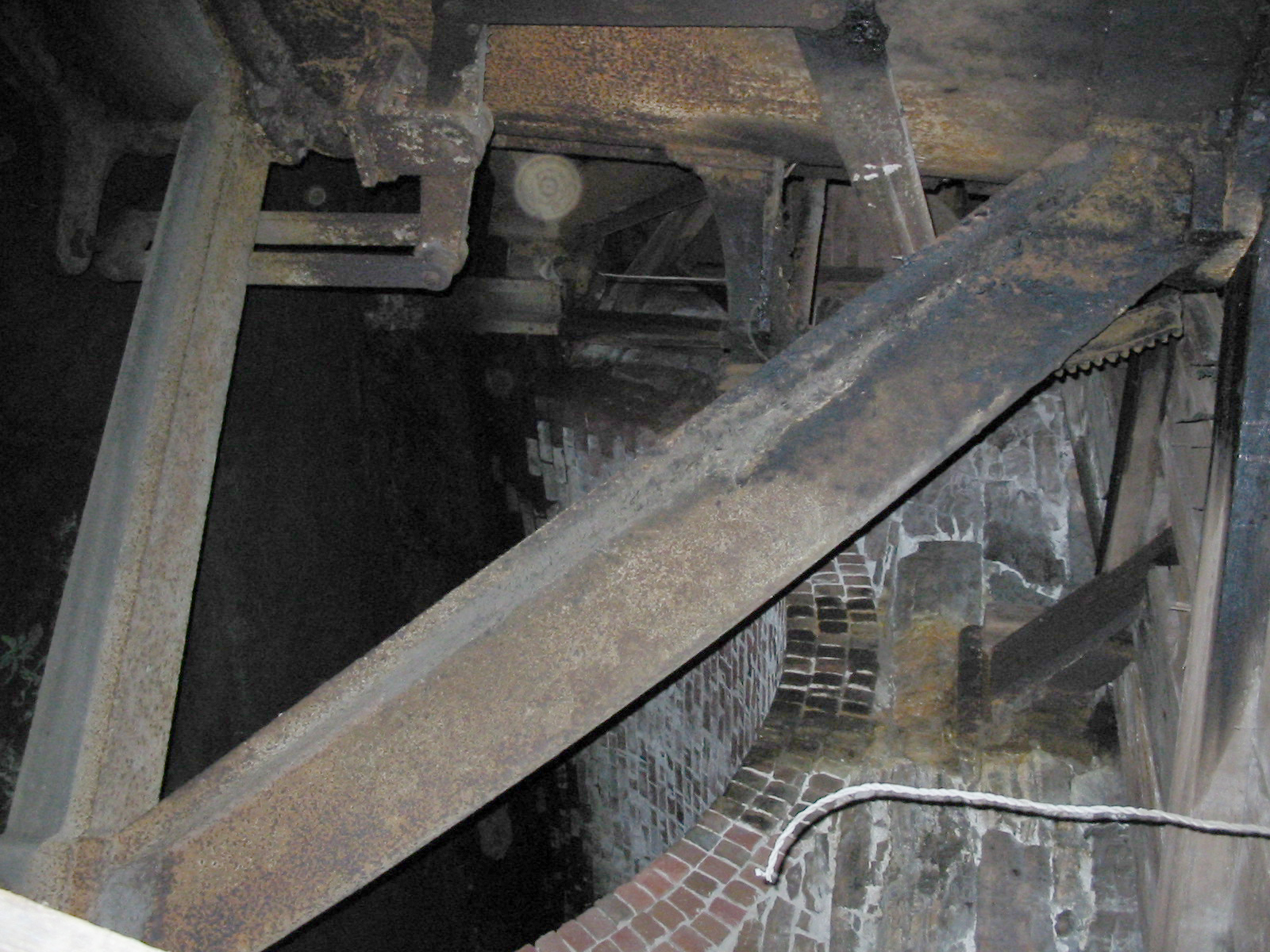
A view of the curved, brick, discharge wall that directs the flow into the tailrace. This curved wall directed the Fourneyron flow into the tailrace channel. The entrance to the tailrace had cast iron slots to install wooden stoplogs. After the logs were installed, this brick cylindrical chamber was pumped out to work on the runner.
(see 1852 Fourneyron side <<< click here).
In order to allow for work on the turbine, being done in the dry, designers elevated the machine above the tailwater of the turbine. A cylindrical pipe was attached to the discharge end of the turbine to convey the water back to the tailrace. The shear weight, of the cylinder of water, created a vacuum at the discharge end of the runner. Since the power extracted from a turbine is a direct function of the drop in pressure across it, the lower pressure, created by the cylinder, effectively increased the total drop.
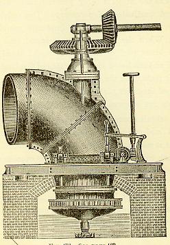
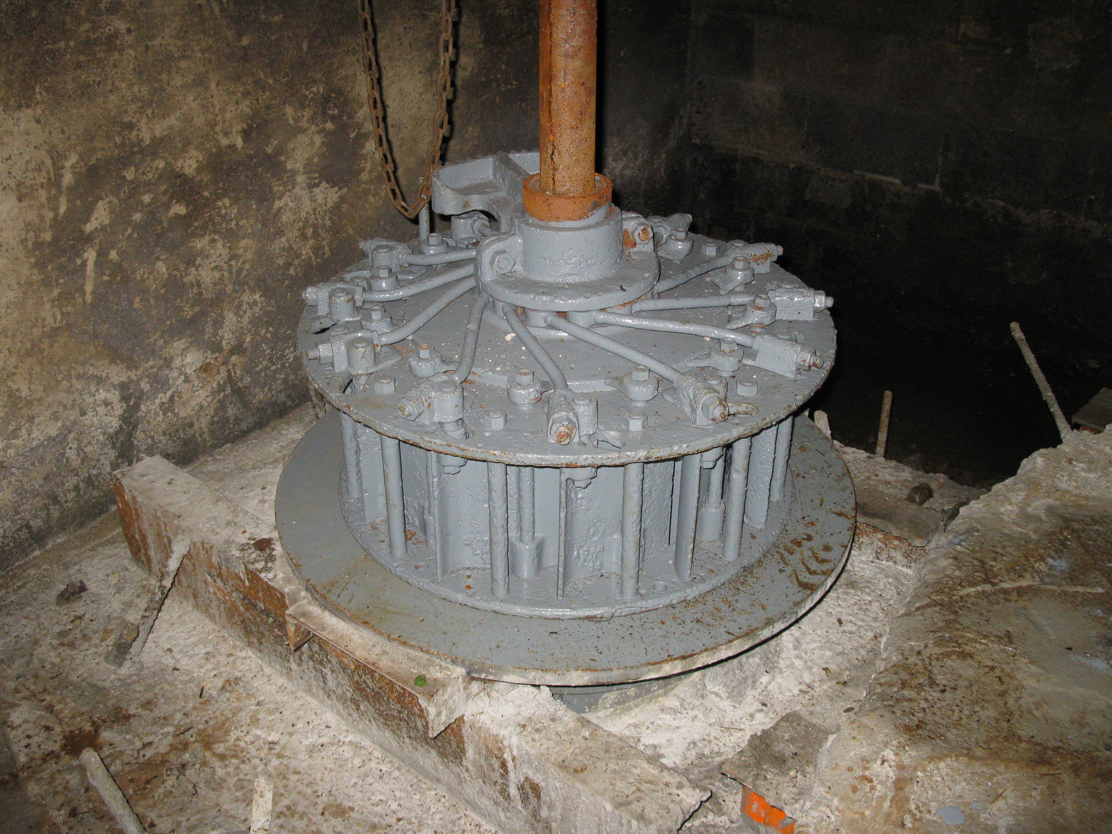
 <<<<<<< Note cylindrical draft tube.
Figure Three: Hercules turbine with cylindrical draft tube. The early American builders were not mathamatical and did not know about Bernoulis' Principle.
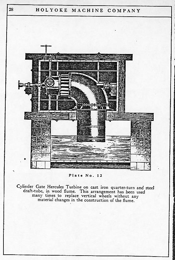
In the early years, prior to the turn of the last century, effective thrust bearings had not been invented. Since the weight of the turbine, turbine shaft, generator rotor and the hydraulic thrust on the runner was very large for wooden (lignum vitae) thrust bearings, most units were designed with horizontal shafts. This put the dead weights on a radial bearing and the wooden thrust bearing only had to support the hydraulic thrust. In order to turn the water, from the horizontally discharging runner, into the vertically discharging cylinder, a 90 degree cast iron elbow was inserted at the discharge of the runner.
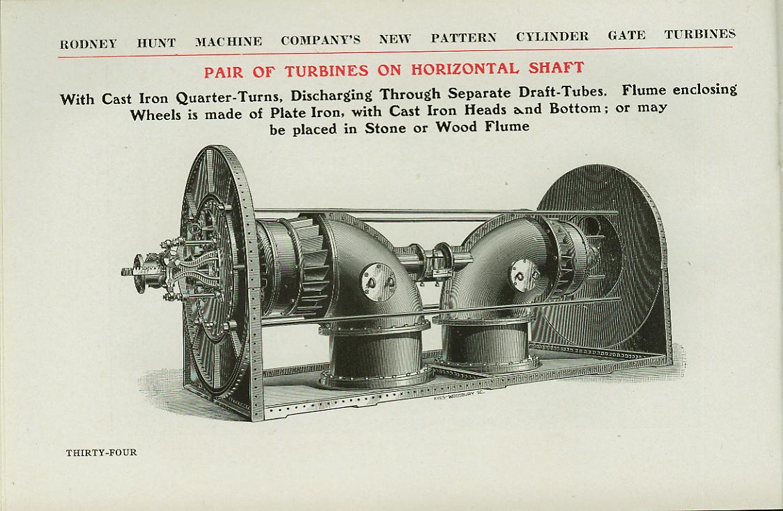
Figure Four: Two runner on a horizontal shaft. This configuration is theoretically balanced, with no end thrust. The dead weight is resting on wooden, lignum vitae, bearings. The hydraulic thrust is also taken up by a wooden, lignum vitae, thrust collar. Since the hydraulic thrust of each runner is pushing against each other there is no resultant thrust. In practice, leaves and debris block one end and a large thrust results.
As turbine designers in the U.S. became more theoretical, it was noted that a serious loss of energy was taking place in the high discharge velocities exiting the cylindrical draft tube. By applying Bernouli’s Theorem, to the flow of water in the cylinder, it was noted that one could recover the velocity head by slowing the water down. The water can be slowed down by exchanging the cylinder for a cone. As the water enters the small end of the cone, it slowly spreads out, as it progresses down the length of the cone. The velocity head is recovered and converted into vacuum head on the discharge end of the runner.
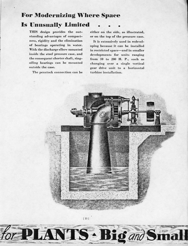
Figure Five: Example of a conical draft tube coupled to a horizontal shaft turbine with a cast iron quarter turn (90 degree) elbow.
The problem is, if you create a cone with too large a 1/2 angle, the water becomes detached from the wall of the draft tube. At the point of separation, you get a high velocity, cylindrical core, passing through the center of the draft tube. Many laboratories, including WPI’s Alden Hydraulic Research Laboratory, investigated separation of flow, in many draft tube shapes, including the simple conical tube (these are also called diffusers).
If you were to take a conical draft tube and project its sides to the apex of the cone (the pointy end of the ice cream cone) the angle between the sides is the draft angle. If you were to measure the same angle between the side and the cone's vertical axis, the angle is called a ½ angle. For design purposes, the ½ angle should not exceed 5 to 7 degrees, to prevent separation of flow.
As the years went by, engineers developed larger and larger sites. In order to keep generator costs down and accommodate a horizontal shaft, turbine manufacturers started adding more and more runners to the horizontal shaft. This became quite bulky. As Kingsbury developed his tilting wedge bearing, it was possible to install the unit with a vertical shaft. The problem was, a vertical conical draft tube to slow the water down, required a tremendously deep excavation. (A good rule of thumb is that the vertical distance from the bottom of the conical draft tube to the discharge pit floor is the diameter of the large end of the draft tube.)
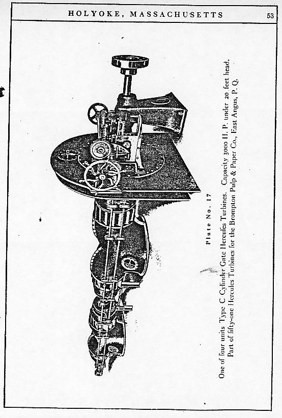
Figure Six: Here are four runners on a common shaft. The rpm stays the same because the diameter is not changing. However, the power is increasing with the number of runners. The dead weight is still on the wooden, radial bearings and theoretically, the thrust is equalized by the runners discharging at the ends of the tee stands. The down side is the length of the turbine pit and draft tube pit is getting longer.
In order to save on excavation costs and effectively turn the water back into the tailrace, the elbow draft tube was incorporated. Here, the water is initially slowed down in a conical draft tube. The end of the cone then turns 90 degrees and a horizontal section conveys the water back to the tailrace. It is interesting that the early American turbine manufacturers kept the cross sectional area of the elbow draft tube expanding along the length of the tube. The problem with this approach is that the water tries to bend around the sharp, inner bend, of the 90 degree section and separates from the wall. You end up with a high speed, horizontal, jet bashing along the floor of the draft tube.
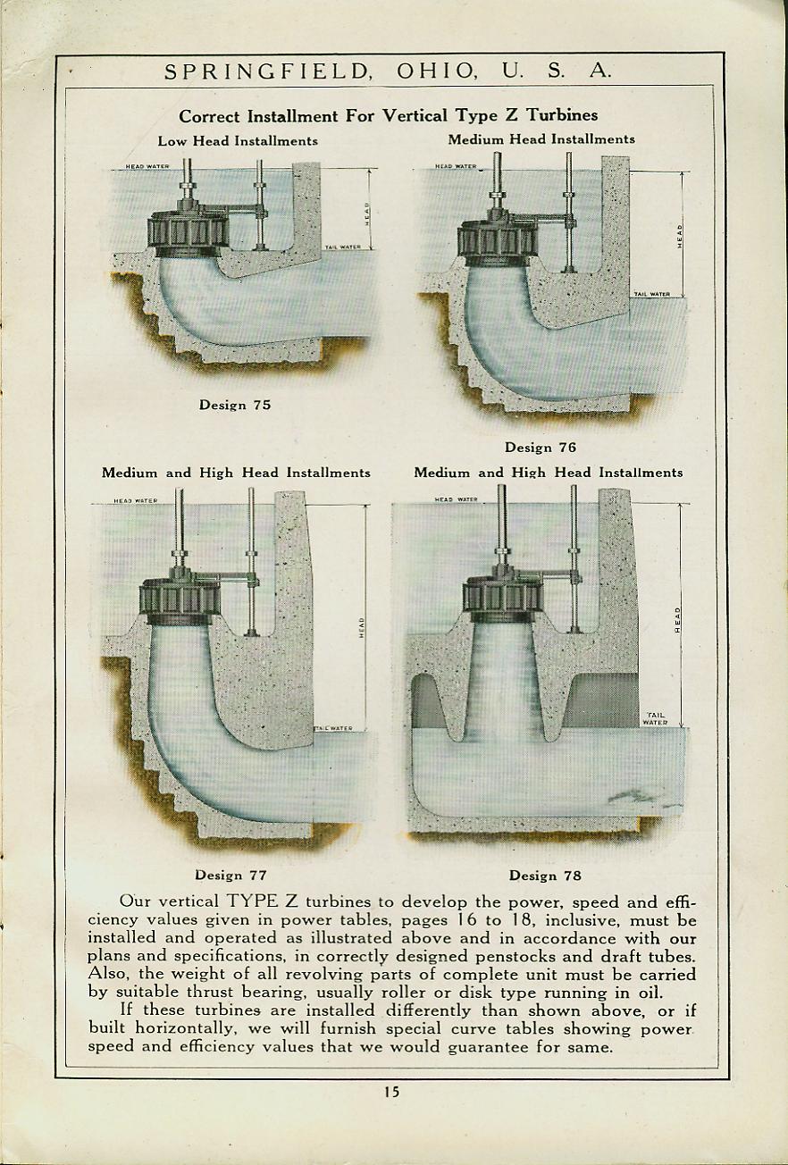
Figure Seven: Various forms of elbow draft tubes
It can be shown that it is impossible to have separation of flow in an accelerating column of water. The European designers cleverly slowed the water down in the vertical, conical section. They then decreased the cross sectional area of the tube through the elbow! This caused the water to accelerate through the elbow and the water stayed attached. They then expanded the horizontal section of the tube back to the tailrace. It is important with elbow draft tubes that at least 18 inches of submergence is created at no flow conditions between the crown of the draft tube exit and the tailwater surface.
I inspected a draft tube for a utility in Maine. They complained that the newly installed unit was not performing. It turned out that the draft tube had not been designed to the correct vertical length. The crown of the end of the elbow was out of water by 22 inches. This allowed air to extend all the way back to the elbow and most of the velocity head could not be recovered.
It is extremely important that the draft tube for a high specific speed Francis runner or a propellor, be properly designed to recover the velocity head exiting from the runner. For these units, 35% of the total head is recovered by the draft tube.
Now, let’s design a simple conical draft tube.
FIGURE ONE: SIMPLE CONICAL DRAFT TUBE
From trigonometry:
Tan theta= rise/run= R0/(X+L)=RI/X
Where:
L= length of the draft tube
RO= outlet radius (big end)
RI= inlet radius (small end)
theta= draft tube ½ angle
Solve for x:
X= RI/Tan theta
Or
(X + L)= R0/Tan theta
X= (R0/Tan theta)-L
Setting X =RI/Tan theta= (R0/Tan theta)-L
L= (R0/Tan theta)-(RI/Tan theta)
= (R0-RI)/Tan theta but R=D/2
= (D0-DI)/2Tan theta
DO= outlet diameter (big end)
DI= inlet diameter (small end)
Previously I said the ½ angle to prevent separation of flow in conical draft tubes should be around 6 degrees.
Inserting 6 degrees into our equation yields:
L= 5*(Dexit-Dinlet)
This is a conservative equation for sizing conical draft tubes for small turbines that do not need the expense of an elbow draft tube.
As an example, Celesty purchased two Leffel, 17A Samson turbines. These are equipped with short conical draft tubes. A bridge tree with a lignum vitae thrust bearing is cast into the end of the draft tube. The losses for this system are high. The draft tube is too short and the bridge tree disturbs the flow in the draft tube. We decided to eliminate the factory tube and installed a 3/8 inch steel plate, conical draft tube. We used a Timken bearing, located on the powerhouse floor, to take the thrust and weight.
From Leffel’s Bulletin 38 at 12 feet of head,
Q17A= 1394 cfm= 23 cfs
Industry practice is one meter per second velocity from the end of the draft tube or 3 feet per second.
For an incompressible fluid, the discharge area is:
Q= V * A or
Area= flow/velocity= Q/A
At 23 cfs, the area is:
A= 23 cfs/3 fps= 7.67 feet square
But:
A= phi* D*D/4 or:
D= (4*A/phi)^0.5
D= (4*7.67)/phi)^0.5
= 3 feet<<<<<<
We measured the discharge end of the runner. Remember to measure the inside diameter of the skirt ring. Do not use the outside diameter. The water flows out of the inside diameter.
The discharge diameter measured with a large caliper was 21.25 inches= 1.77 feet.
From our formula, L= 5*(Dexit-Dinlet):
L= 5*(3.00-1.77)= 6.15 feet or 74 inches.
And that’s what we made!!!!!!
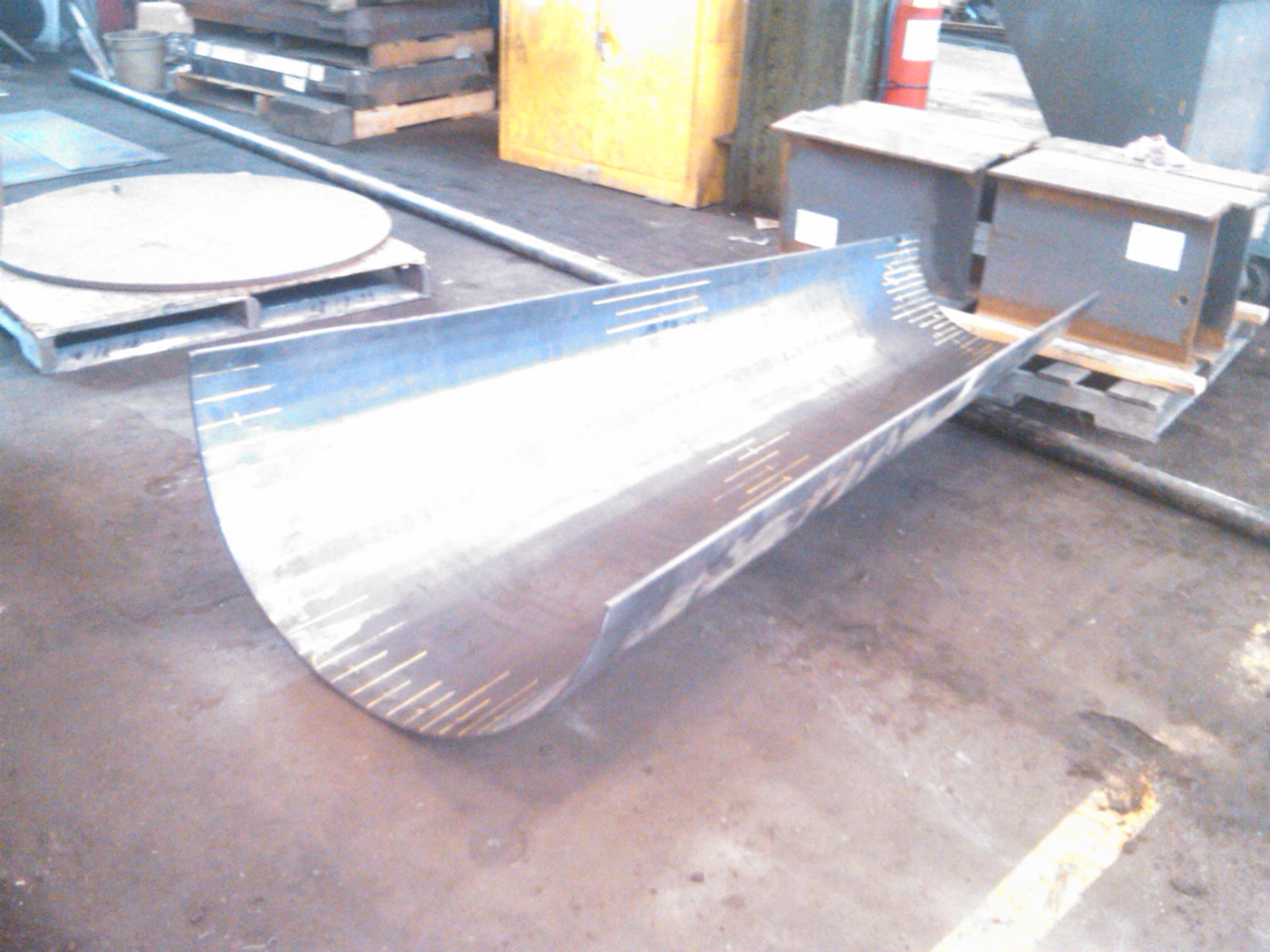
Here is Celesty's draft tube being rolled at the fabrication shop. It is more common to roll the tube as a series of progressively larger cones and butt weld them together. Mike Piesyk of Industrial Steel & Boiler, of Chicopee, Ma realized he could roll two axial shells and weld the longitudinal seams to complete the fabrication. After is was welded, he installed the turbine throat ring and flange to complete the design.
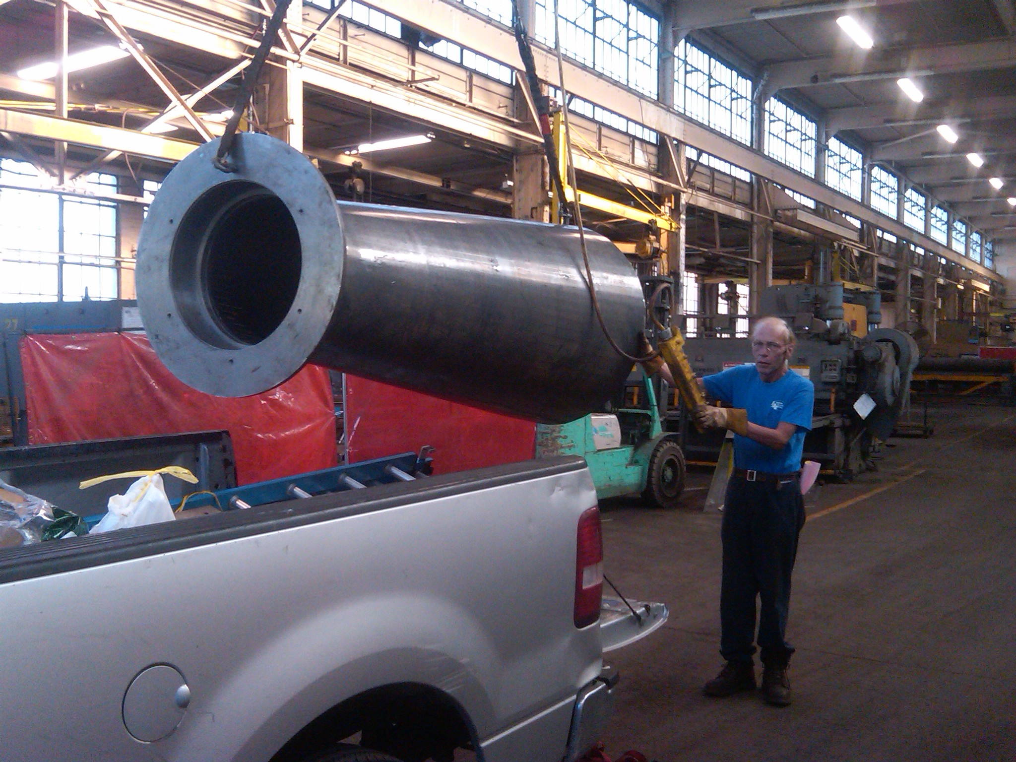
Here Mike Piesyk and I are loading the completed draft tube into my trusty Ford F-150 for the trip to our Tannery Pond site. Note the cylindrical throat and flange we designed to match the little Leffel Samson unit. Note the small step at the bottom of the throat. This step matches the size of the Samson runner's skirt ring. The inside diameter of the step matches the inside diameter of the turbine skirt ring (Dinlet) so that the water slides seamlessly out of the runner and into the draft tube.
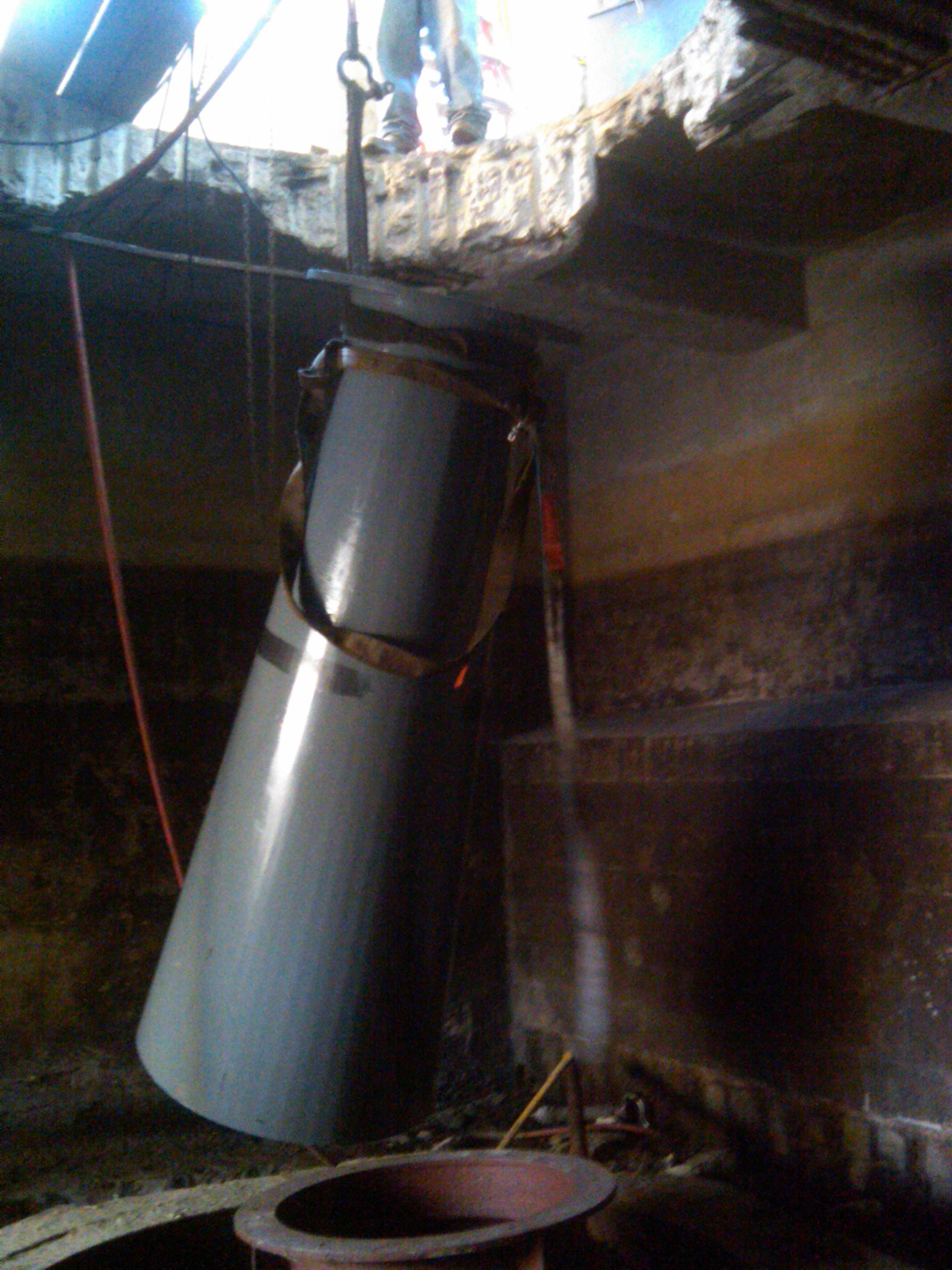
Here is Celesty's little draft tube being lowered into the waterbox. The red draft tube is for our Leffel 18 inch "Z" turbine. It is resting in the steel thimble that housed the Leroy Somers tube turbine.
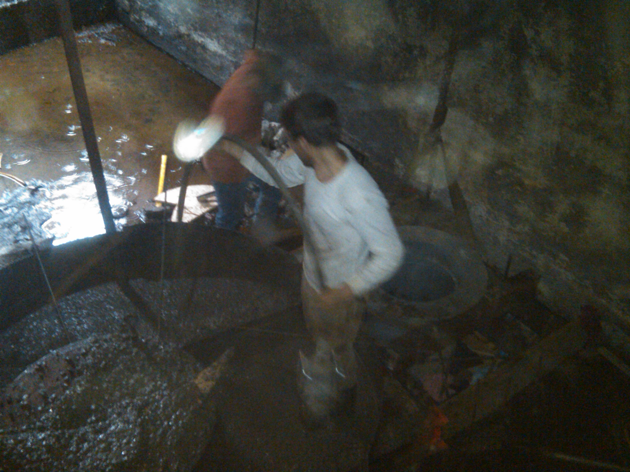
Here we have leveled the two draft tubes. We set them on I-beams and installed steel shims between the I-beams and the draft tube flange. We used a Starrett 12 inch, Master Precision Machinists Level that has an accuracy of 5 ten thousanths of an inch per foot to complete the leveling. We then poured the concrete around them. Note Celesty's little draft tube is setting on the steel leveling I-beams. We have installed a wooden form underneath the powerhouse to keep the concrete in.
Here is the 17 A Samson turbine sitting on top of Celesty's draft tube ready for its final layer of grout. We grouted in between the I-beams. We made a stiff mix of concrete and sloped it up to the I-beams to allow the water to slip into the turbine wicket gates.
To everyone, my friend Tony Murtagh, in France, has been very interested in using a Moody Spreading Cone Draft Tube at his small site. He has tried everywhere for the design information. I am so proud of him!!! In dispair, he found a free computerized fluid dynamics (CFD) model and modeled the draft tube by himself!!! He had never used a CFD model before. I attach herewith in its entirety the e-mail he sent to me. You too can be a fluid dynamicist!!! I apologize that the pictures did not appear! I will find out why and repair the e-mail.
Bill,
I am trying to do the CFD (Computational Fluid Dynamics) analysis of the Hydraucone Draft Tube.
I am using open source software, OpenFOAM.
Some preliminary results are shown below.
I have managed to generate the pretty pictures, streamlines, velocity maps etc.
The next challenge is to quantitatively compare the efficiency of various design.
Yours,
Tony Murtagh
*********************************************************************
Subject: ParaView Questions
Bruno,
Thank you very much for your tutorial on energy flow measurement in ParaView.
I have tried your methods. They were very useful.
I am trying to compare two draft tubes - one with the deflector plate (AJM21) and one without the deflector plate (AJM22). The inlet and outlet conditions were the same for both simulations.
The initial results of these two simulation have been shared with you via Google. They were not run for large number of iterations so the results may be a litle inaccurate. I assume they are adequate to make rough comparisons between the two designs.
AJM21 With Deflector Plate


The boundary conditions are very simple. These are the limitations of the Khamsin plugin for Google SketchUp.
Patch 7 is the Inlet
Patch 5 is the Outlet
Patch 6 is the Deflector Plate
AJM21 Patch 5 Outlet Velocities at Patch 5 (Outlet)

Calculator for U.U
Is this the dot product of the two vectors ? Does this give the square of the velocity orthogonal to the Outlet (Patch 5) ?

Integrate the varialbes


As expected the Area is 10 (m2). The Pressure is 0, as set in the boundary condition.
With a flow if 10m3, the average outlet velocity should be 1.0 m/s.
The integrated U value is 7. Does this imply an average velocity of 0.7 m/s.
Perhaps I need to integrate the component of U that is orthogonal to the Outlet. How do I do this ?
Is it Sqrt(U.U) in the Calculator ?
How do I measure the flux across the Outlet ? Is it Integrated value of the component of U that is orthogonal to the Outlet ?
The Integrated value of (U.U), labeled "VSquared, is an interesting number: 18.6. I belive this is a good indicator of the kinetic energy flowing across the Outlet. (V2/2g)
When I repeat the exercise for the Draft Tube without the deflector, I get very interesting results.
AJM22 Without Deflector Plate

The boundary conditions are the same as AJM21.
Patch 5 is the Outlet
Patch 6 is the Inlet
AJM22 Without Deflector Plate Velocities at Patch 5 (Outlet)

The Integrated values (including V Squared) are:


The Integrated value of (U.U), labeled "VSquared, is an interesting number: 15.9
Does this imply that there is less kinetic energy leaving the draft tube in this case ?
Perhaps I need to calculate the ratios of the Integrated "V Squared" at the Inlet to the Outlet.
Your suggestions, advice and guidance would be greatly appreciated.
Yours,
Tony Murtagh
House 00 33 3 84 62 89 53 Mobile 00 33 6 77 89 02 61