 GREEN
GREEN
AND
CLEAN
POWER
French River Land Company's Website!
|
AND CLEAN POWER French River Land Company's Website!
|
|
French
River Land Company's Home Page!
Rebuilding 120" Niles Boring Mill HYDROELECTRIC SITES: Anasagunticook Lake Dam Replacement- C.Fay & W.Fay Appleton Wisconsin Anniversary Senor Bonifettis' sites in Chile Turners Falls Generator Rewind USEFUL ENGINEERING: Admitting Air to Turbine Runners Improves Efficiency, S. Logan Kerr Air Admission to Hydro Runners, David Cox, USCOE, Kerr Dam Archimedian Screw Pump Handbook- Gerhard Nagel A Self-Adjusting Spring Bed Bearing- Henry G. Reist ASME 1646 The Banki Water Turbine Mockmoore and Merryfield Bearing Currents: Their Origin and Prevention C. T. Pearce Bishops Method- STABGM Program Blade Pitting- Boving LTD 1930 Cavitation- Accelerated Research, Allis Chalmers Research Cavitation & Vibration of a Draft Tube Cavitation- Prevention & Reduction, Allis Chalmers Research Causes & Effects of Cavitation in Hydraulic Turbines Chain Turbine by: Nguyen Minh Duy Chain Turbine Mechanics- Discussions with Duy Characteristics of Modern Hydraulic Turbines-Chester Larner Comparative Tests On Experimental Draft Tubes- C M Allen & I A Winter 1923 Design of an Overshot Waterwheel (by Carl Weidner) Design of Small Water Turbines for Farm and Small Communities Design of the runner of a Kaplan turbine for small hydroelectric power plants: Timo Flaspöhler Draft Tubes of Hydro-Electric Stations by M. F. Gubin Ejection into Tailraces of Hydropower Plants: S. M. Slisskii Erection & Alignment of Vertical Waterwheel Generator Units-R.O. Standing Evolution of Hydraulic Prime Movers-Byron McCoy Fall Increaser Herschel Venturi Tube Fall Increaser Moody Ejector Turbine Fall Increaser Hydraulic Jump Apron Generator Shaft Design Calculation- Olav Hodtvedt Governor Theory for the Plant Operator Graphics of Water Wheels- William Fox Hydraulic Motors- M. Bresse & F. A. Mahan 1869 Hydraulic Power Transmission by Compressed Air Hydraulic Rams their Principals and Construction by J. Wright Clarke Hydraulic Turbine and Governor Field Erection Information Hydraulic Turbines- Robert Long Daugherty Hydraulic Turbines by Arnold Pfau Hydraulic Turbines Gelpke & Van Cleve Hydrokinetic Energy in Massachusetts, William D. B. Fay HYDROTURBINES DESIGN AND CONSTRUCTION N. N. KOVALEV Impulse Turbines by Ely Hutchinson Interference fitting a large runner shaft Kaplan Blade Design NACA Air Foil- Report No. 460 Kaplan Blade Design NACA Air Foil- Report No. 628 Kaplan Design Marko Kogovsek.xls A Laboratory Study to Improve the Efficiency of Crossflow Turbines- N. Aziz & V. Desai Loading Vertical Thrust Bearings R. C. Johnson Low Head Hydroplants, Emil Mosonyi Meggering Earth Resistance Motors as Generators for Microhydro, Nigel Smith Operation & Maintenance of Hydro-Generators Out Gassing of Cross Flow Turbines Parallel Operation of Turbines Analysis Powerhouse Design- Miniwatt Hydro Rack Design-Chicopee-Olav Hotvedt Rack Design- Hydraulic Institue of Munich Rack Design-Flow Induced Vibrations Selecting Hydraulic Reaction Turbines BUREC Snows Improved Water Wheel Governor Standard for Hydraulic Turbine and Generator Shaft Couplings and Shaft Runout Tolerances Stoplog Structure Design Calculation Stress Analysis of Hydraulic Turbine Parts, BUREC- F.O. Ruud Some Fluid Flow Characteristics of a Cross Flow Type Hydraulic Turbine- Durgin & Fay Technology of Heavy Electric Machine Building HydroGenerators Tenth Census of the US, 1880, Water Power of the US, Part I- Professor Trowbridge Tenth Census of the US, 1880, Water Power of the US, Part II- Professor Trowbridge Tests on a Kaplan Hydraulic Turbine Theoretical Conditions Related to an Open Channel Flow Linear Turbine- Ishida & Service Theory of Turbines- De Volson Wood Tidal Energy for Hydroelectric Power Plants by L. B. Bernshtein Treatise relative to the Testing of Water-Wheels and Machinery, James Emerson 1879 Trash Rack Differential Equations 2L/3 Trashrack Differential Equations General Solution f(x) Turbine Water-Wheel Tests- Robert Horton Turgo, A High Speed Impulse Turbine- Paul Wilson Water Hammer and Surge Tanks G. V. Aronovich Water Hammer-Lorenzo Allievi-Text Water Hammer-Lorenzo Allievi-Figures Water Hammer-ASME Symposium 1933 Waterpower Engineering-Daniel Webster Mead Water Turbines Contributions to Their Study, Computation and Design-S.J. Zowski TRADE CATALOUGES: ASEA- Bearings for Large Vertical Hydro-Electric Machines Bradway Turbine (progressive gate) Christiana Machine (register gate) Electric Machinery Company (EM) General Electric- Standard Specifications for Hydro Thrust Bearings and Runners Head Gate Hoists- S. Morgan Smith J & W Jolly (cylinder gate) Lombard Direct-Connected Oil Pressure Governors Bulletin N0. 113 October 1st, 1912 Lombard Governor Company Type T Instruction Book Lombard Governors for Waterwheels and Steam Engines-1902 Lombard Water Wheel Governors Catalouge 26 Ridgway Perfection Water-Wheel Vertical Shaft Water Wheel Driven Generators- General Electric Westinghouse Small Vertical Waterwheel-Driven A-C Generators, July 1944
Links:
Small Turbine Manufacturers Websites: www.waterturbine.com
|
Livermore Falls Web Page
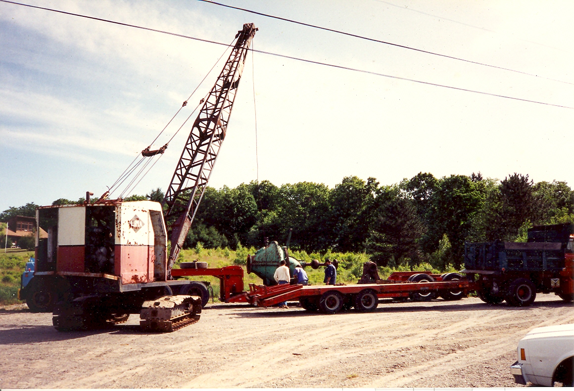
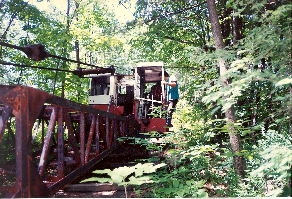
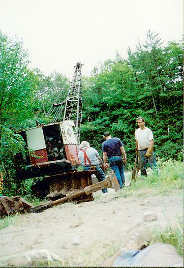
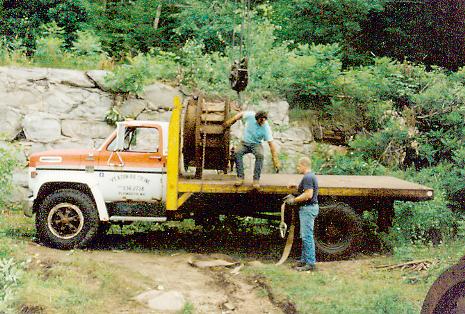
We purchased the turbines, at Livermore Falls, from the property owner. The problem was, that in six months, the property was being sold to the State of New Hampshire and turned into a state park. We needed a crane to remove the equipment. I had never operated a crane. We found this one, in a field, in West Boylston, MA. We bought it for $ 1200.00. It had not run for twenty years. We changed all the fluids. Here, we have hired a truck to bring it to Plymouth, New Hampshire. Here, I am driving the crane, for the first time and I am crawling it up onto the trailer deck. When it got to the top of the ramp, it tilted quickly forward, onto the horizontal deck. My heart was in my mouth. Little did I know of the terrors to follow.
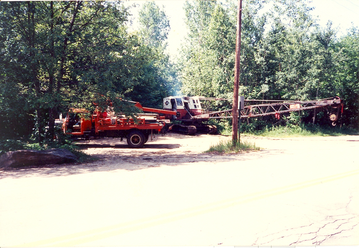
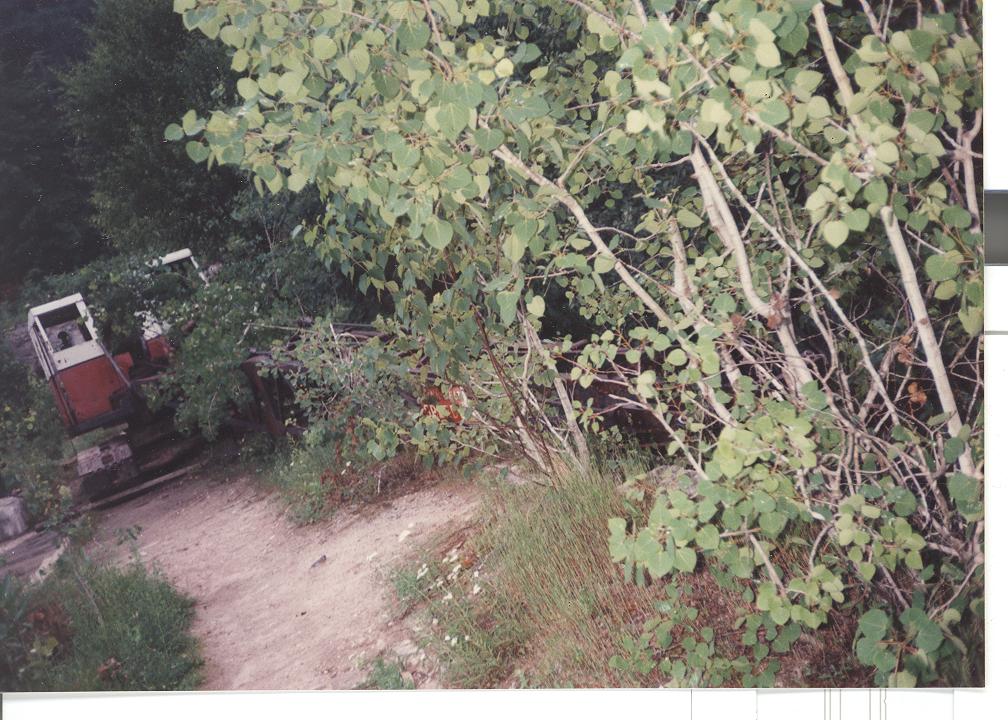
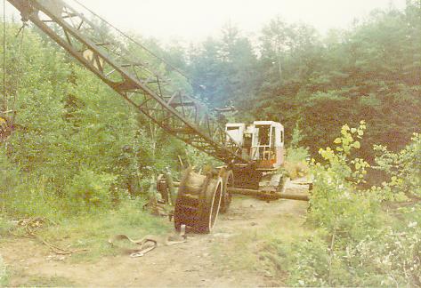
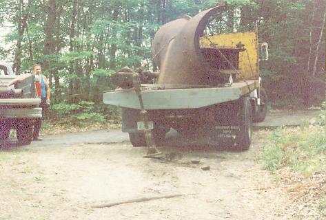
Here we are, five hours later, at the top of the gorge, at Livermore Falls, Plymouth, N.H. This is at the head of the old mill driveway. The driveway had deteriorated, since 1955, when the mill closed. It was a lonely feeling, watching the trailer return to Massachusetts with out us!
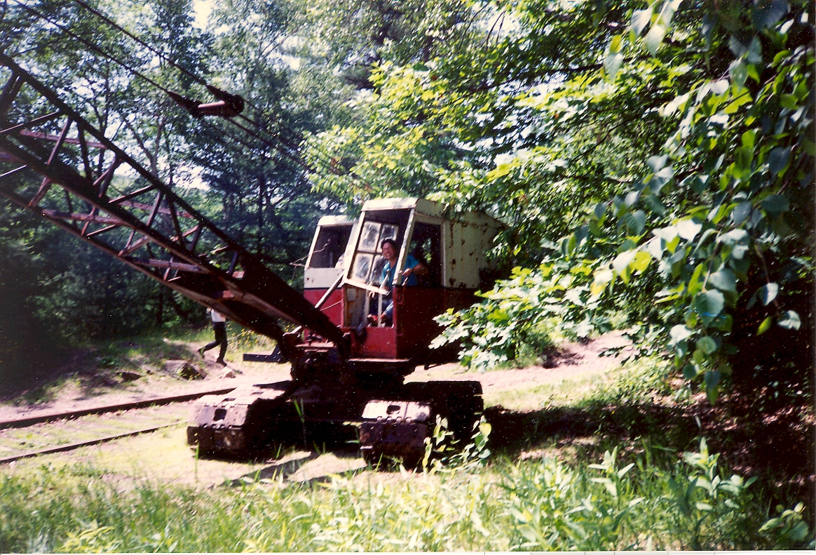
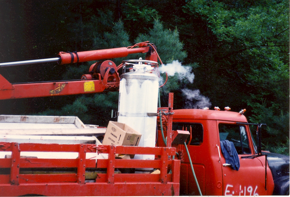
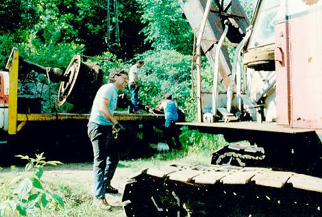
Another picture of the crane and our cherry picker at the side of old Route 3. Note the tank of liquid oxygen behind the cherry picker's boom. The first thing we did was to drop the crane boom down. We removed the boom's sheaves, to make new bronze bushings, at our friend, Dave Dearborn's shop.
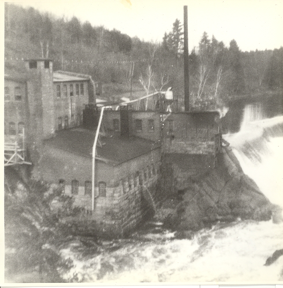
A picture of the pulp mill circa early 1950s Note the guard rail posts on old Route 3 at the upper left.
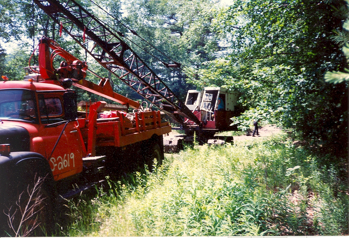
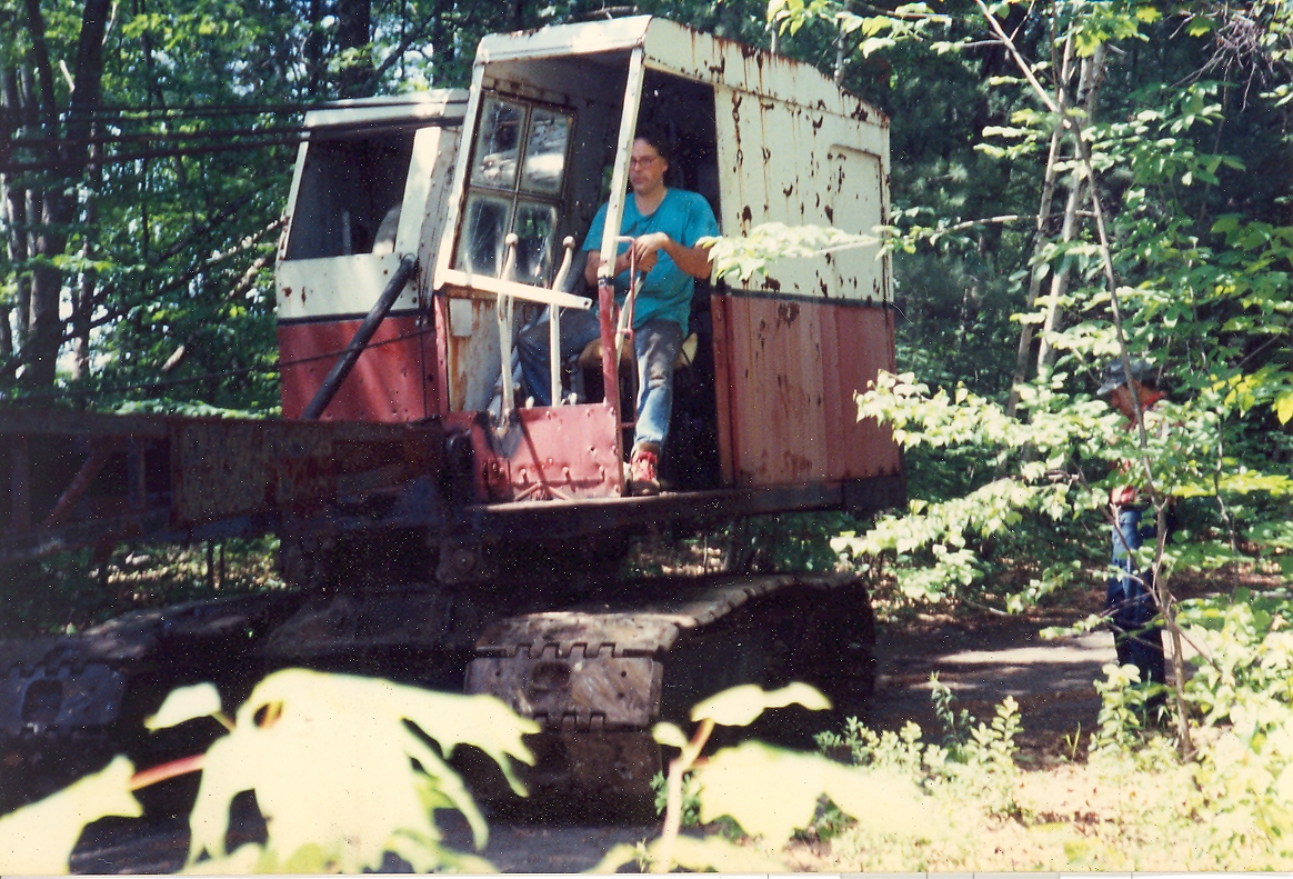
I am crawling, the crane, down the remains of the mill driveway. It has deteriorated into a mountain trail. Here, I am taking a break, after realizing that crawler cranes do not have brakes. Note the timber that Davis has tossed in front of the tracks to slow me down. I quickly realized that you use the reverse gears and slip the clutch as you slowly roll down the side of the mountain.
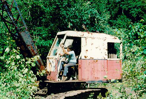
That's me!! Look at my face, is that a look of concentration or one of stark terror?
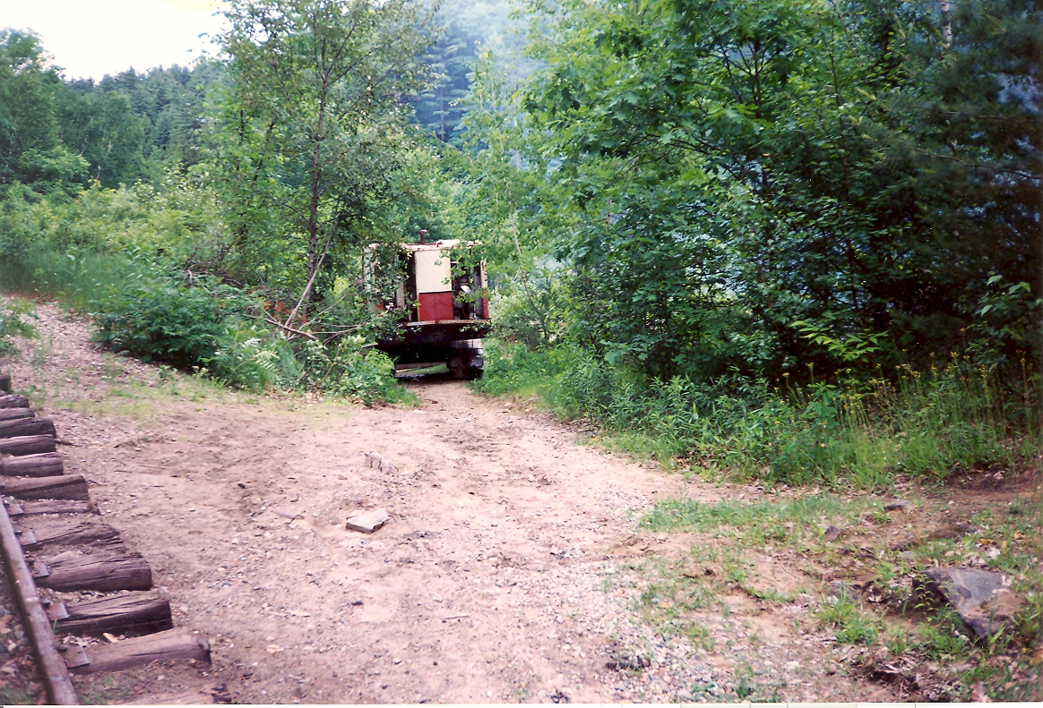
We now need to cross over the Hobo Railroad's tracks. We built up the space between and on either side of the tracks with timbers and crawled over the tracks.
Here is the tricky part. The crane is 12 feet wide and the road is ten feet wide. There is a shear drop of 60 feet on the river side. I slowly crawled around the corner.
At the edge of the abyss. This a great place to learn how to operate a crawler crane with no one to teach me how.
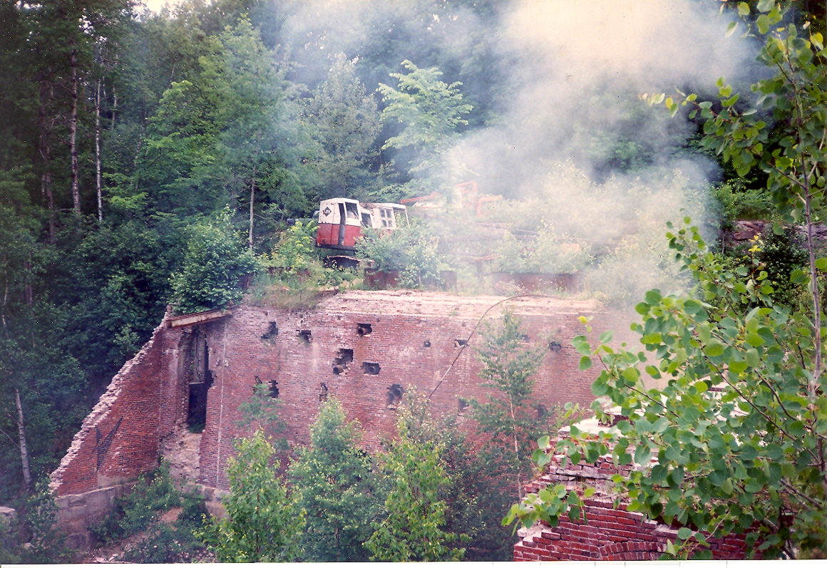
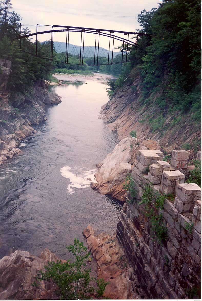
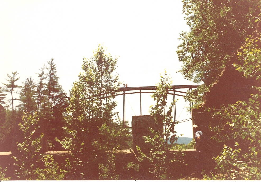
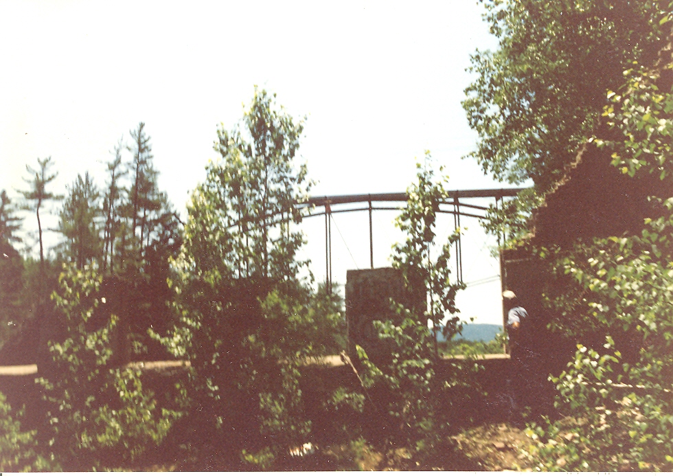
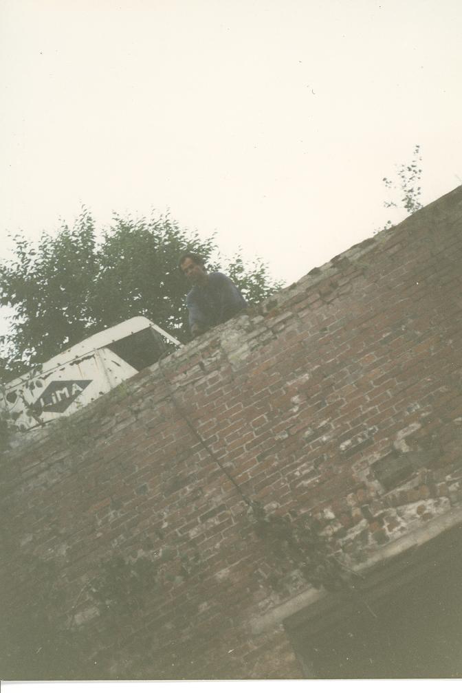
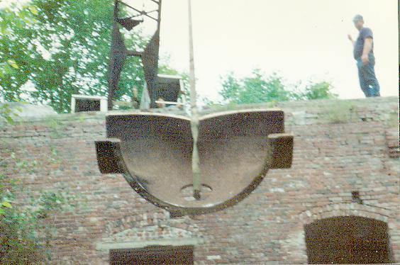
The ruins at Livermore Falls. We needed to cross over the roof, of part of, the mill remains. The LIMA 34 remained parked until we determined if the roof is strong enough to support the weight of the crane. We stayed close to the railroad retaining wall and crossed over safely. I walked out on the bridge and dropped a tape to the river surface. It is 104 feet from the bridge deck to the water. One day, while Davis and I were working, we saw two boys on the bridge deck. We were horrified to see them leap off the deck!!! As we scrambled, up the cliff, to get an ambulance, we saw them swim back to the river bank. They subsequently climbed back up and jumped again!! I caught them in the following photos as they jumped.
Two dare devils, about to jump 104 feet, for the second time. Note Mr. Hobbs on at the right watching in disbelief!!!
Note, in the upper center, the boy's body in mid flight. I used to get a thrill, jumping 60 feet, off the second cross, of the railroad bridge, at Wachusetts Reservoir, before they tore it down, but I would never do 104 feet!! One day we saw a scuba diver in the river. We asked him what he was doing. He said that the college kids frequently jumped with their watches and jewelry on. The impact would rip the watches from their wrists. He was recovering treasure!!!
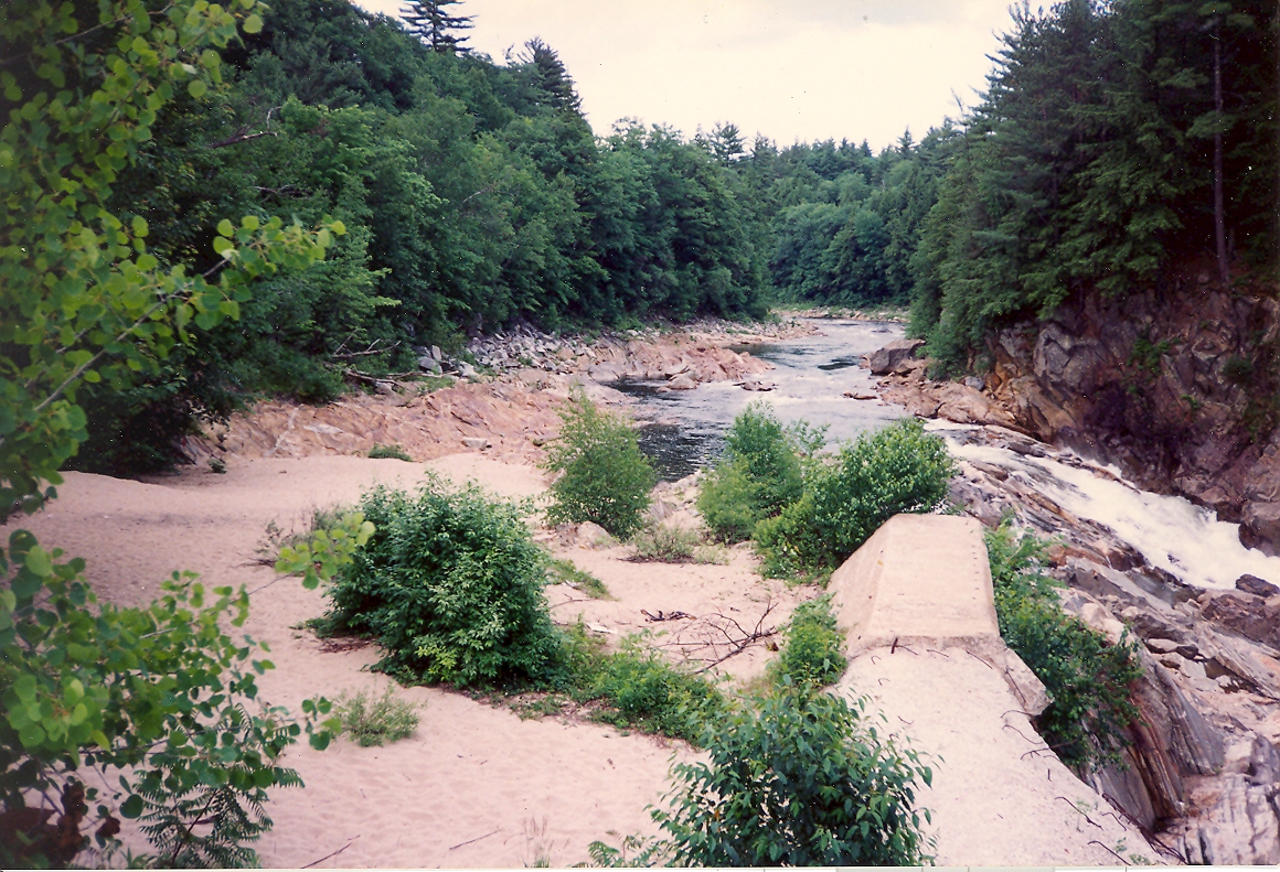
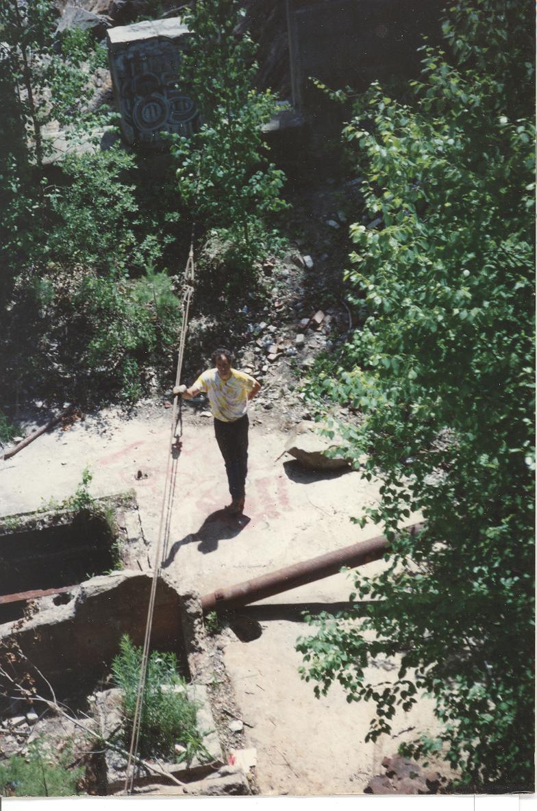
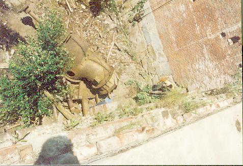
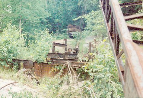
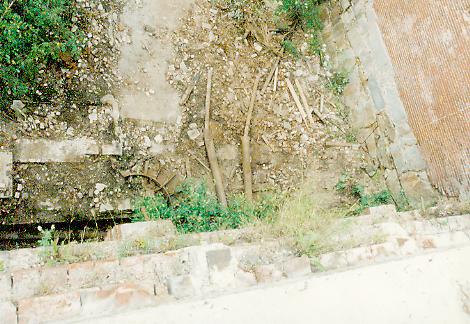
Looking upstream at the remains of the impoundment. The wall on the right is the forebay training wall. The timber crib dam was an extension of this wall and met the river bank on the far side. The dam washed out in 1973. The sandy area, on the left, is the filled in forebay that lead up to the wooden gates. This sand is 25 feet deep. The kids from Plymouth State College use it as a beach. The turbines were originally installed with this area drained. They were lowered down with a crane and rolled into the pits through the gates. We realized, that it would be prohibitively expensive, to dig this area out, so we could pull the turbines out. We decided to concentrate on the front side, where the mill basement used to be.
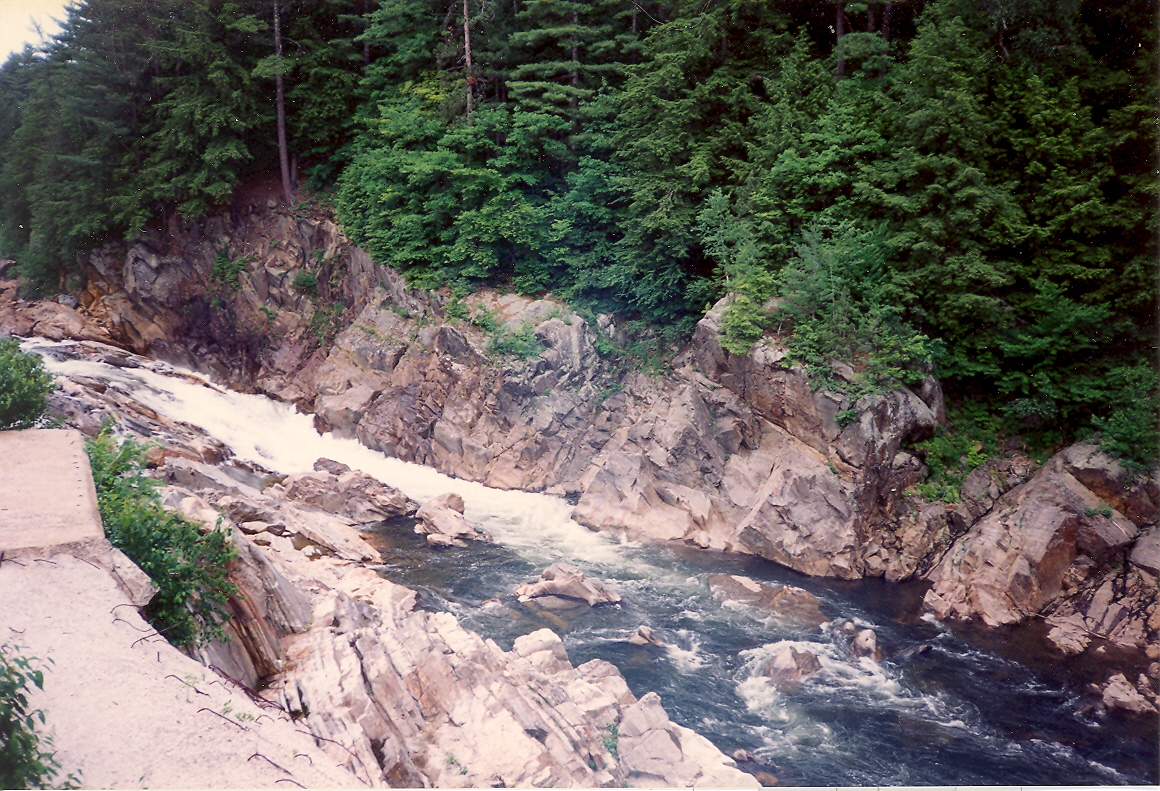
The gorge! No one has ever run this section successfully. There have been fourteen documented deaths.
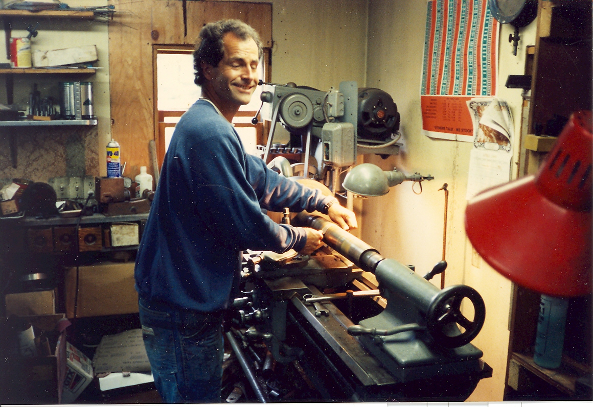
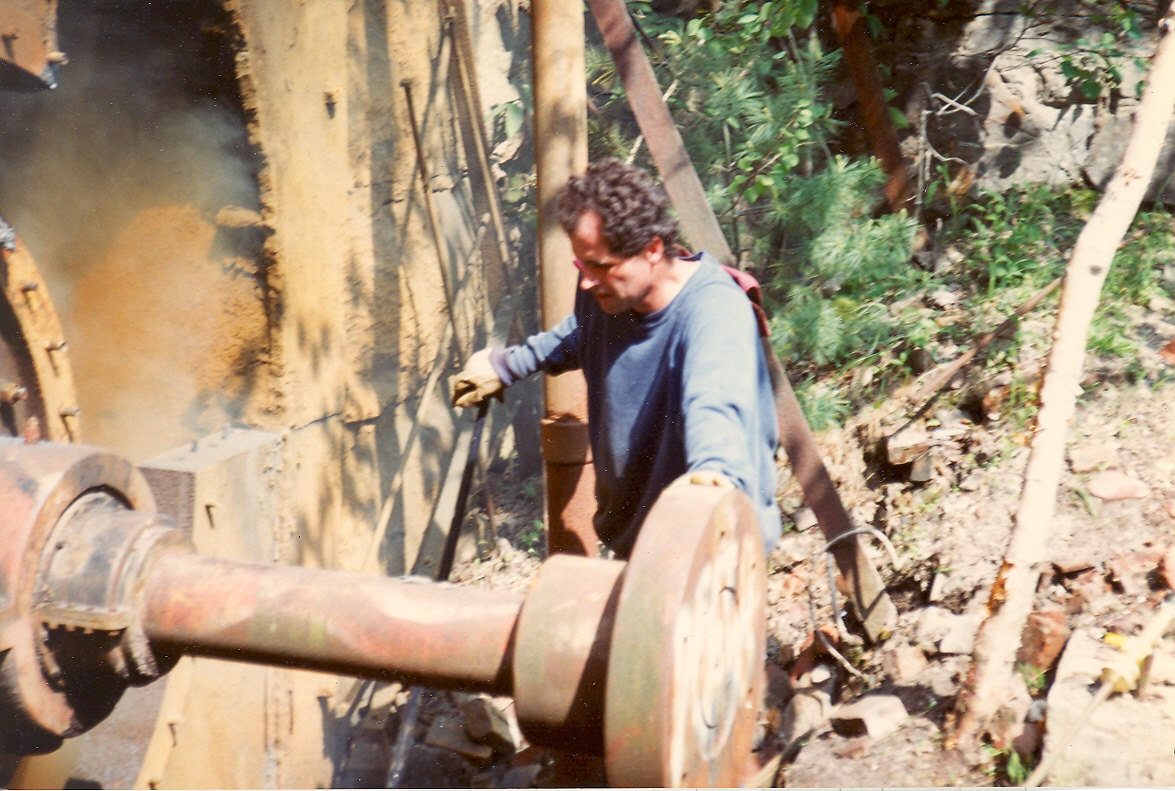
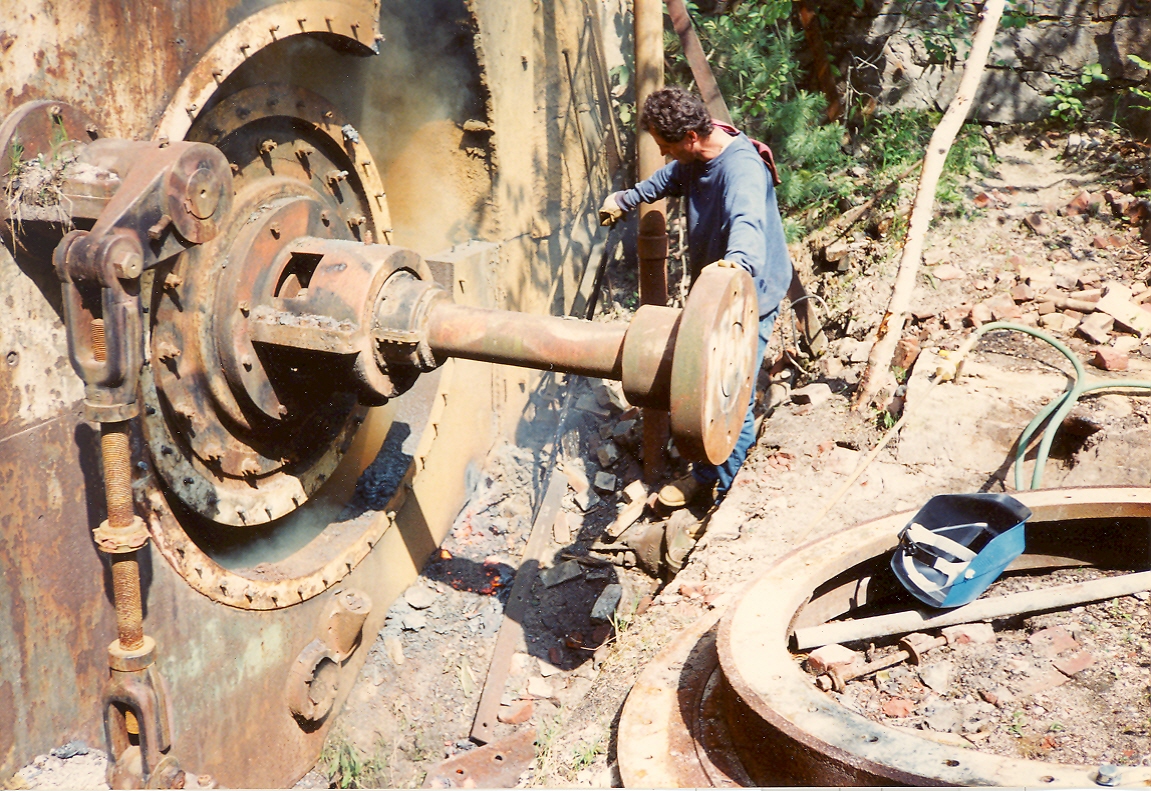
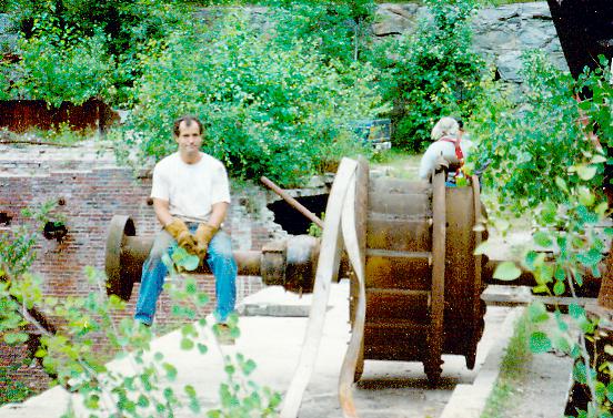
Davis is polishing the LIMA 34's main sheave axle.
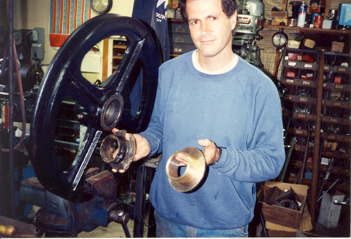
Davis took a solid piece of bronze stock and made the new sheave bearings. He cleaned up and repainted the main sheaves and than pressed in the new bearings. Davis had never used a lathe before. I was very proud of him. This was done in Dave Dearborn's shop.
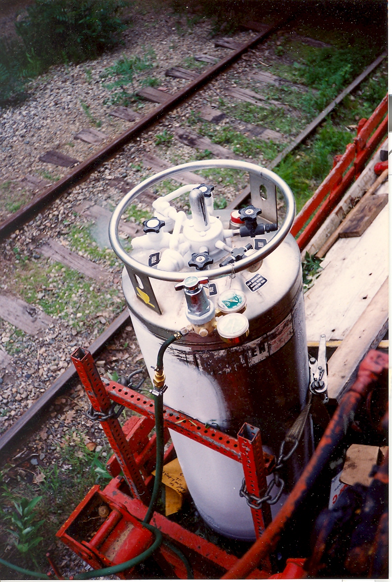
Here is our tank of liquid nitrogen. Note the condensate from our heavy use.
Minus 300 degrees F. This will cool a six pack in 6 seconds. It will freeze the six pack solid in ten seconds!!!
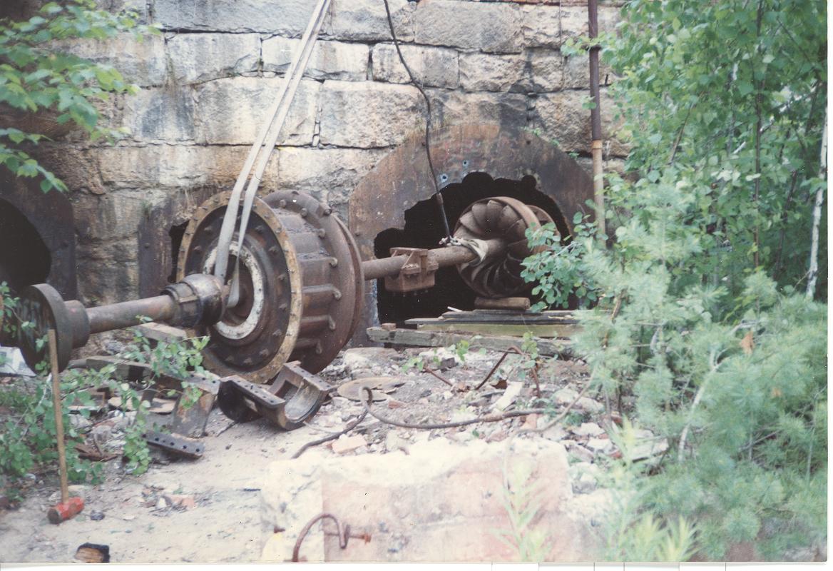
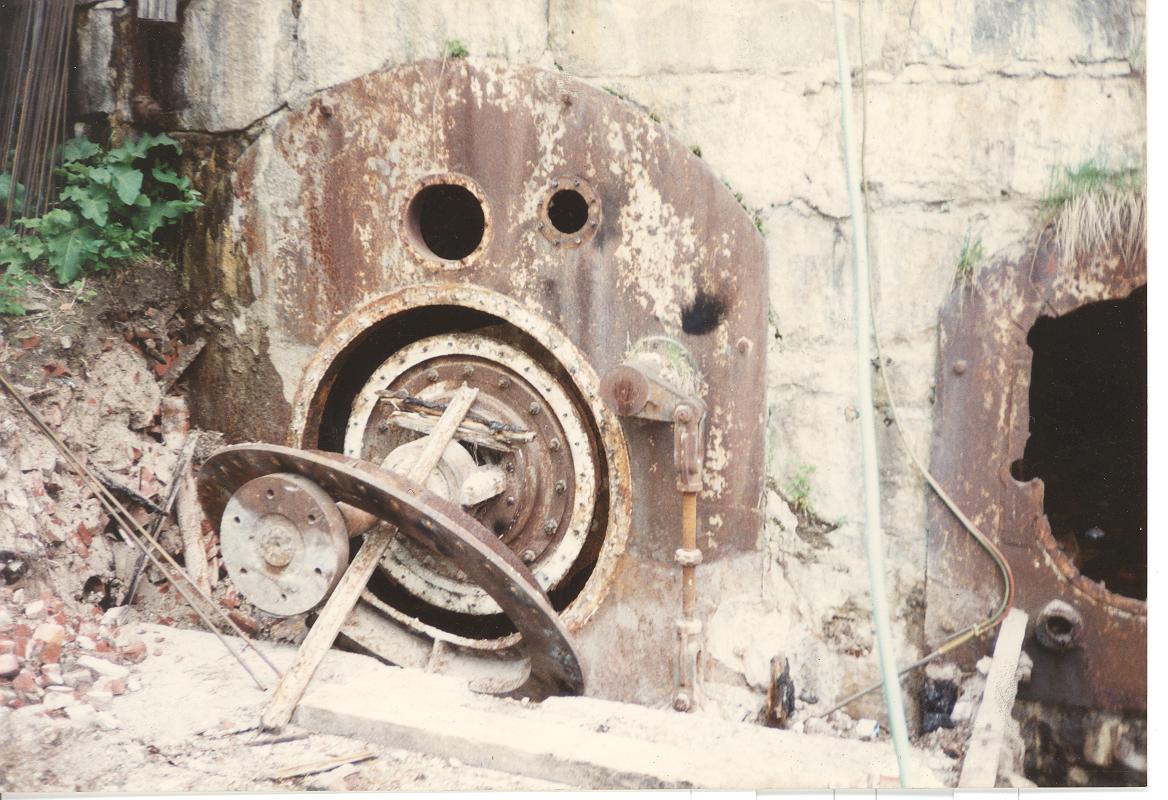
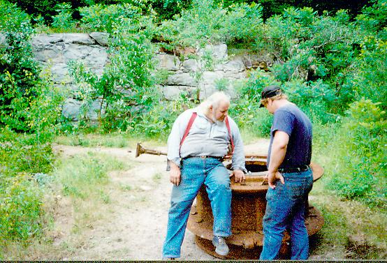
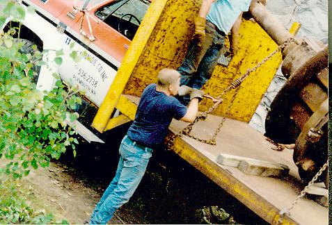
The riverside turbine is exposed. Mr. Hobbs inspects the waterbox door to locate the next cut.
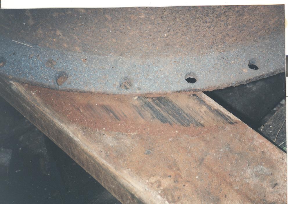
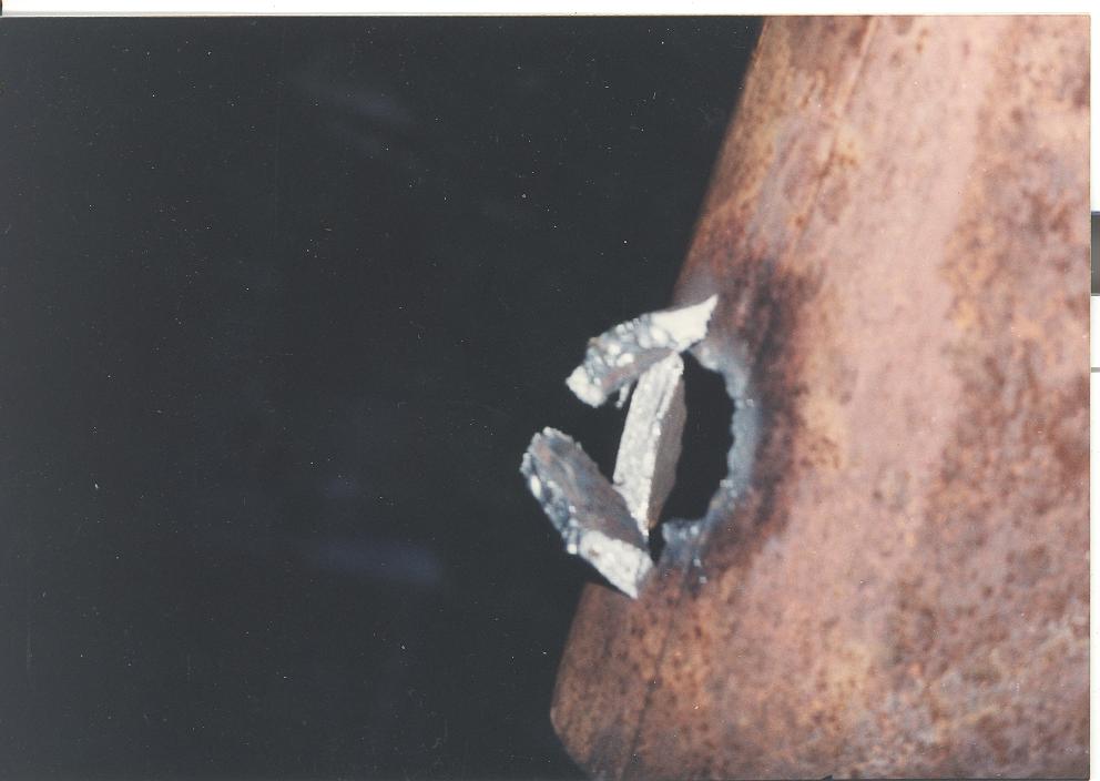
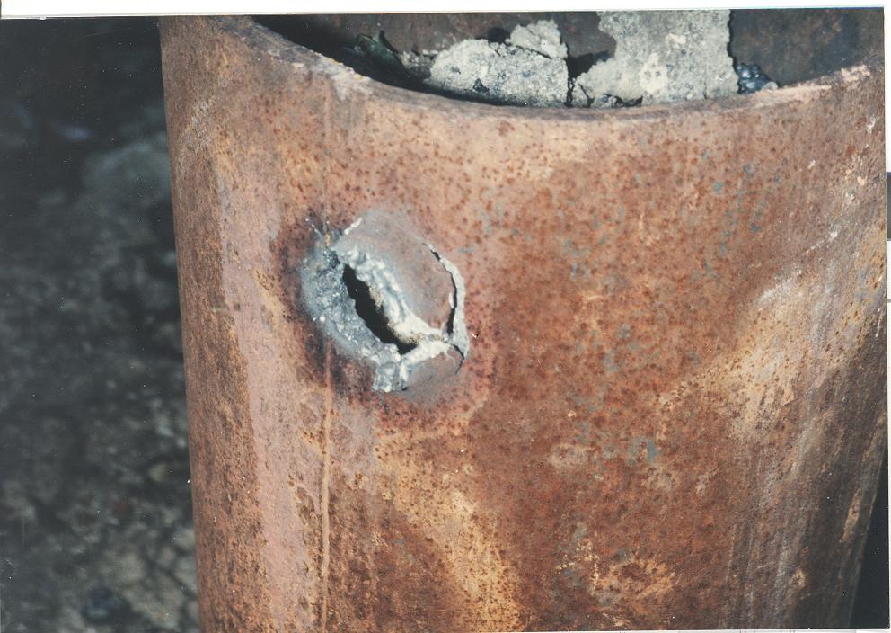
Note how thick the cast iron is. You can not burn cast iron with oxyacetylene.
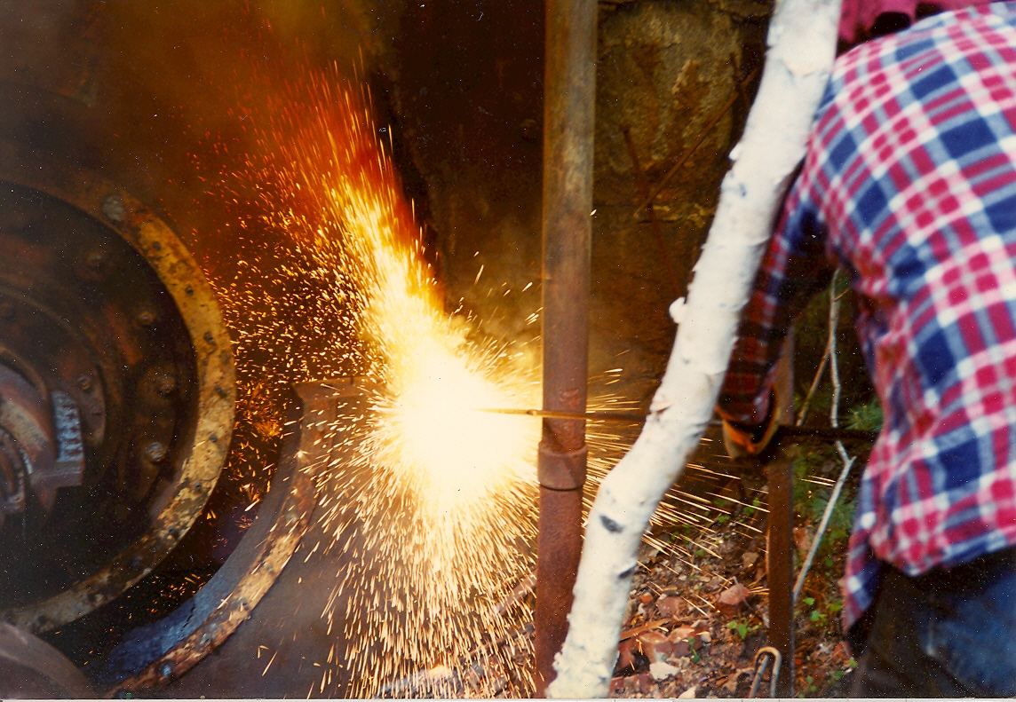
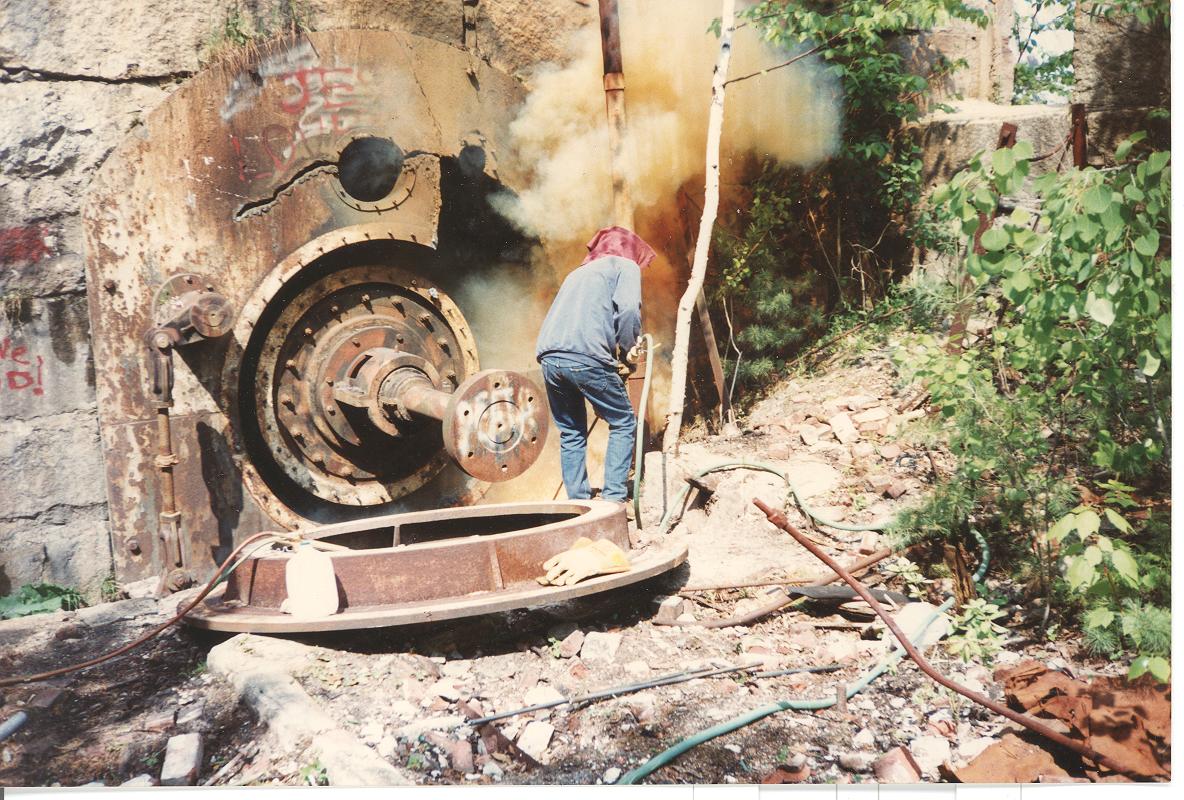
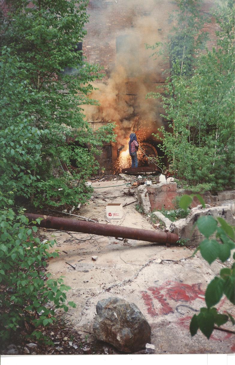
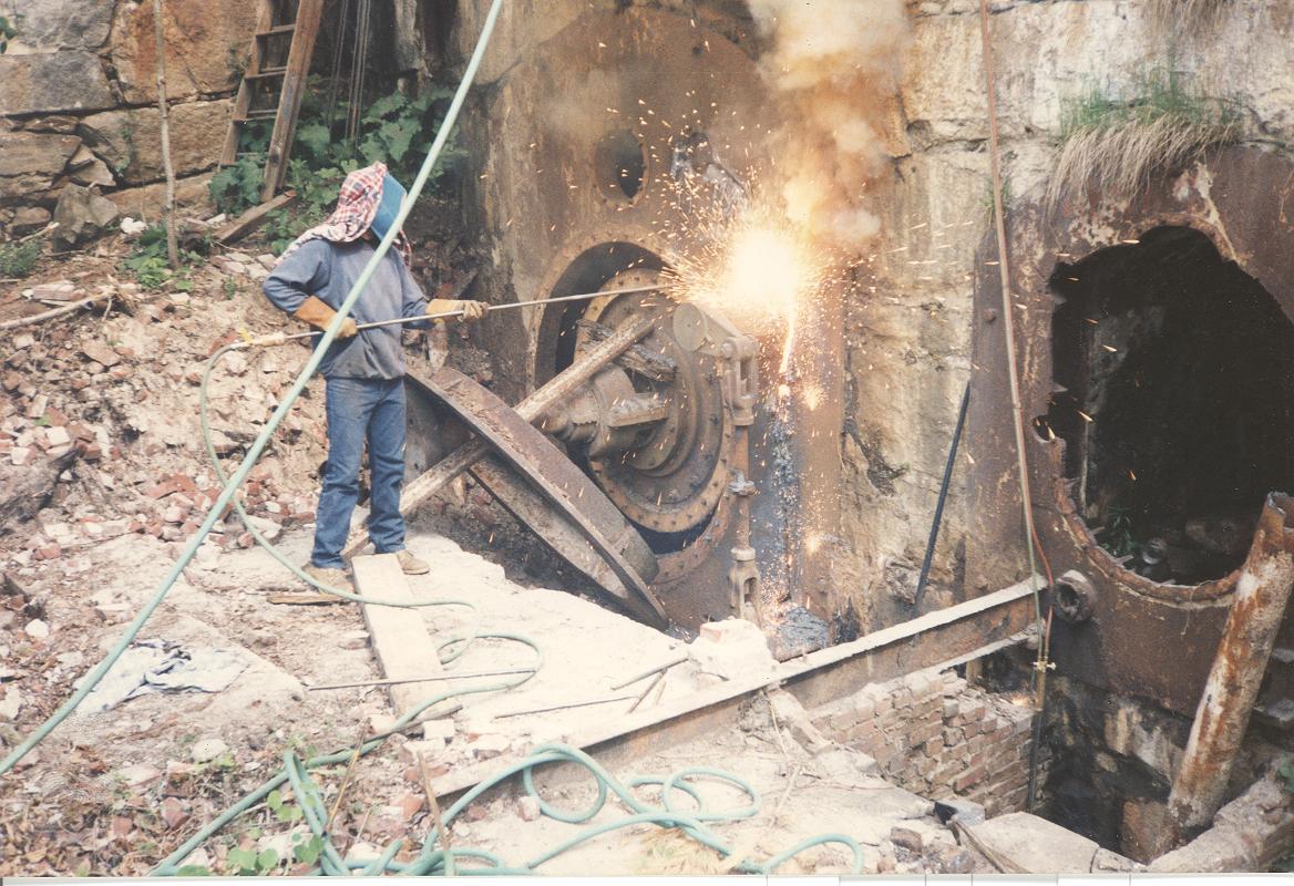
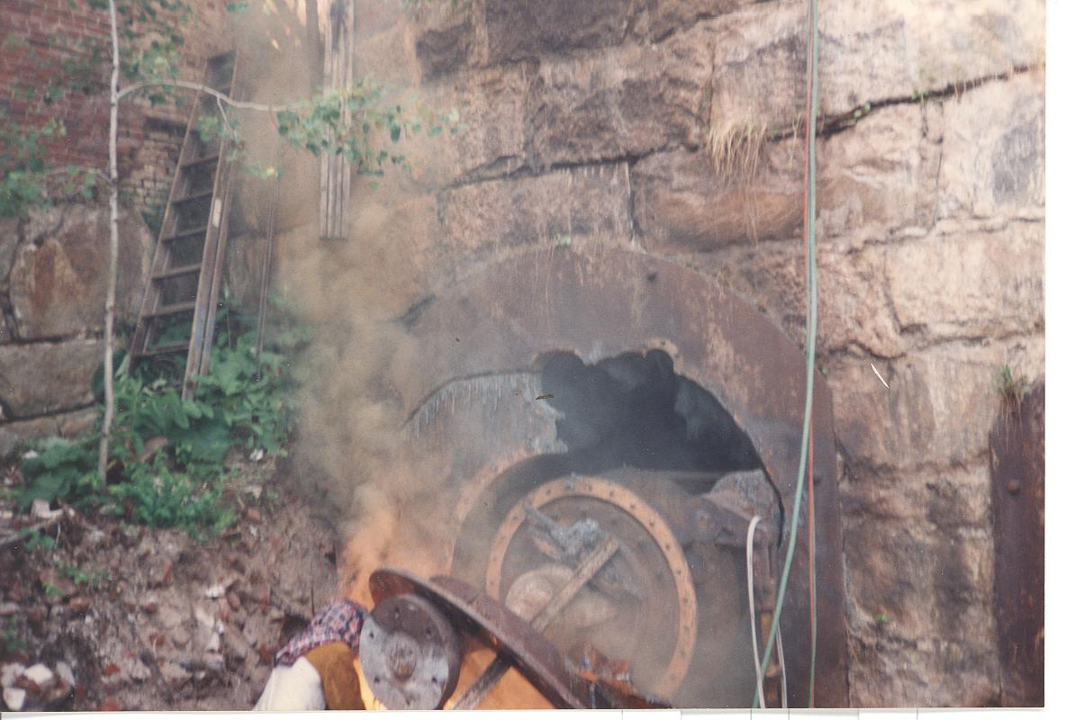
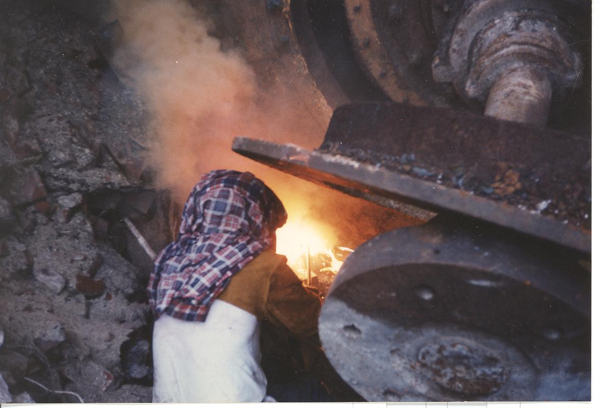
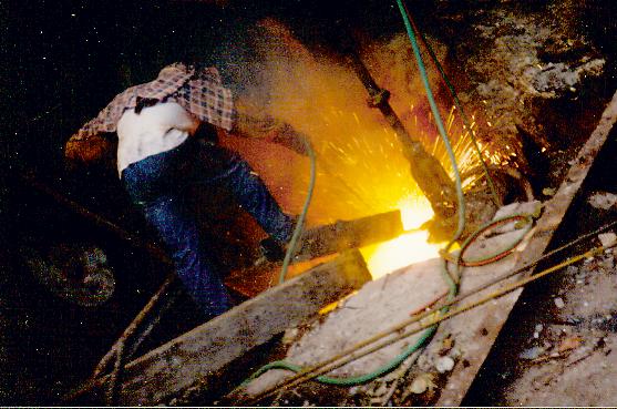
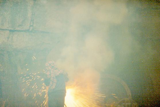
Removing the Rodney Hunt turbines at Livermore Falls, N.H. Bill Fay is using thermite bars to burn the 3 inch thick cast iron head covers at Livermore Falls. Here the cold of outer space (liquid oxygen at minus 297 degF) is feeding the fires of hell (OxyAcetylene burns steel at 2500 degF, the surface temperature of the sun is 16,000 degF. The tip of the thermite bar runs 8,000 degF). The thermite bars are consumed like a punk stick. As they burn down the 8,000 degF gets very close to your hands!! Once they are ignited, we could carve our initials in solid granite.
The amazing thing about this pictures is the smoke. It is gaseous iron!
We had to put our shirts, soaked in water over our heads to protect our scalps. We had a special face mask that allowed us to see. With an ambient temperature of 102 deg F, we could only do three bars and than we had to switch off. We were afraid our clothes would ignite. When we stopped and took our heavy clothes off, even though it was over 100 def F, we started shivering uncontrollably. One bar would do about 14 inches of cut through three inch cast iron.
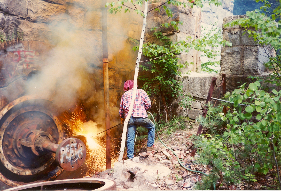
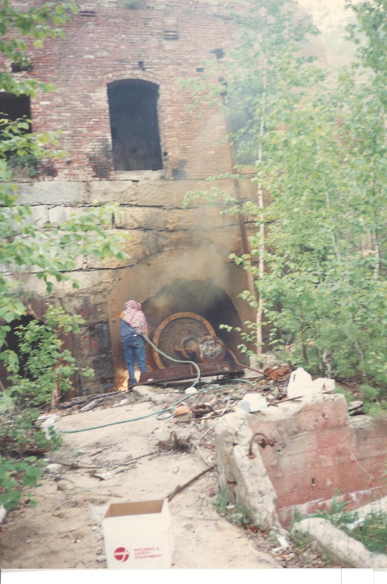
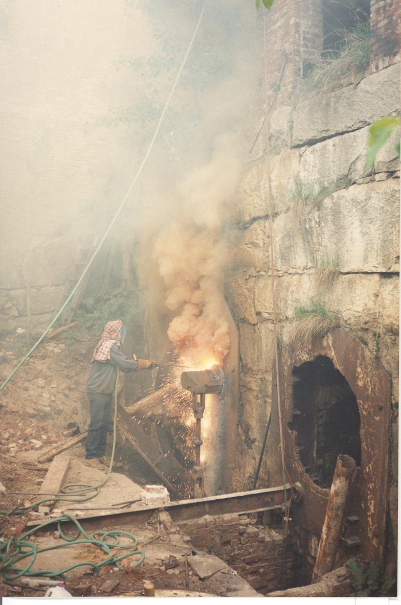
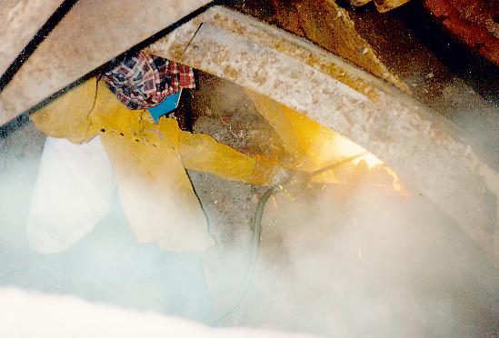
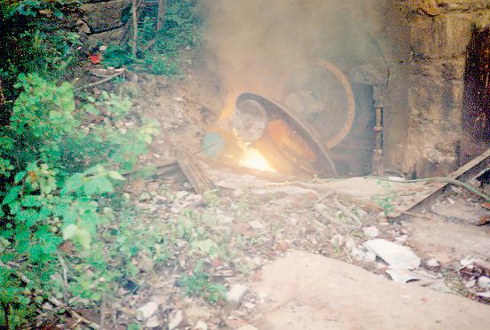
This process took some time. Day after day, we got lost in our little world. One day, we heard a commotion. We looked up and there were about 30 fire and police personnel watching us. The look out tower, on Tenney Mountain, saw our smoke plume and thought the gorge was being incinerated. They called in the troops, to put out a major forest fire. When they got to Livermore Falls, all they found were two crazy guys playing with fire!!
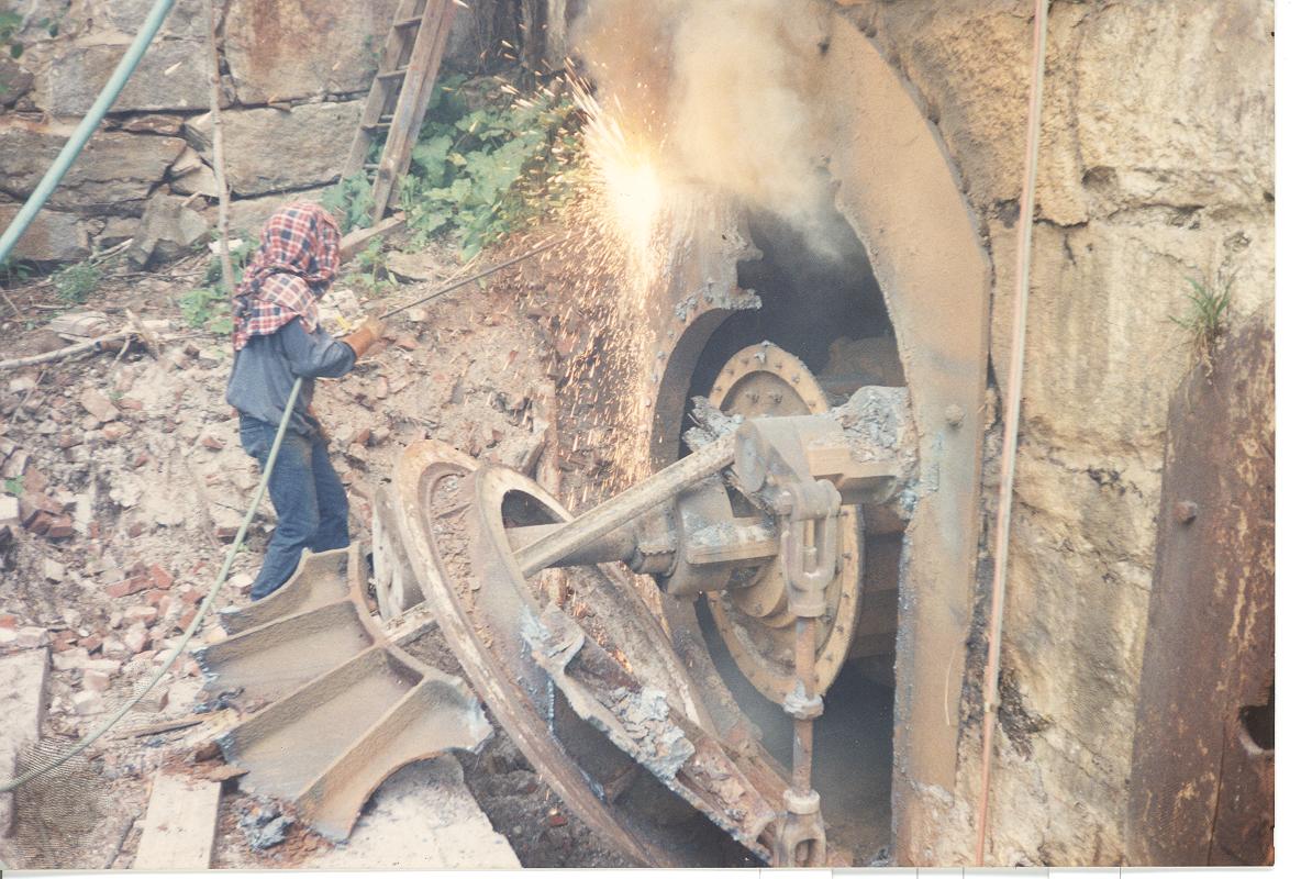
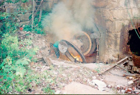
Davis continues to carve an opening.
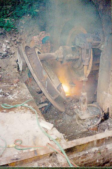
Note the green, high volume, welding hose feeding the burning bar collet. The collet is a cylindrical brass holder. One end has a ball valve to control the flow. The other end has an adjustable collet that the bar is inserted into. When the bar is consumed, the collet is twisted loose, the stub is removed, another bar is inserted and the collet is twisted the other way to seal the sides of the bar.
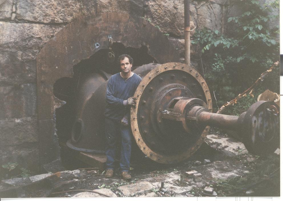
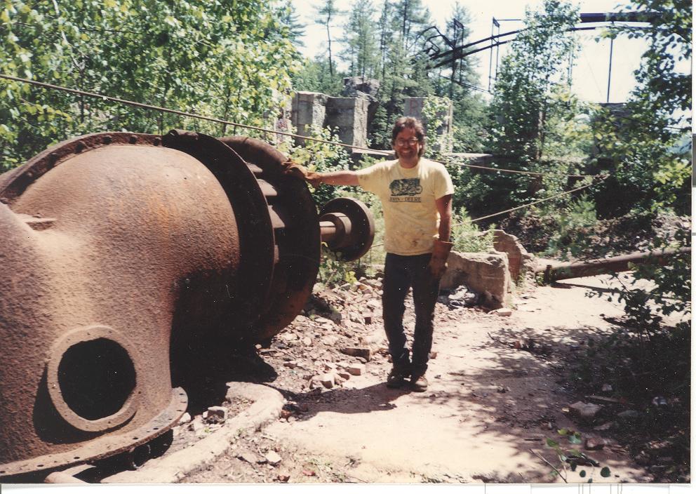
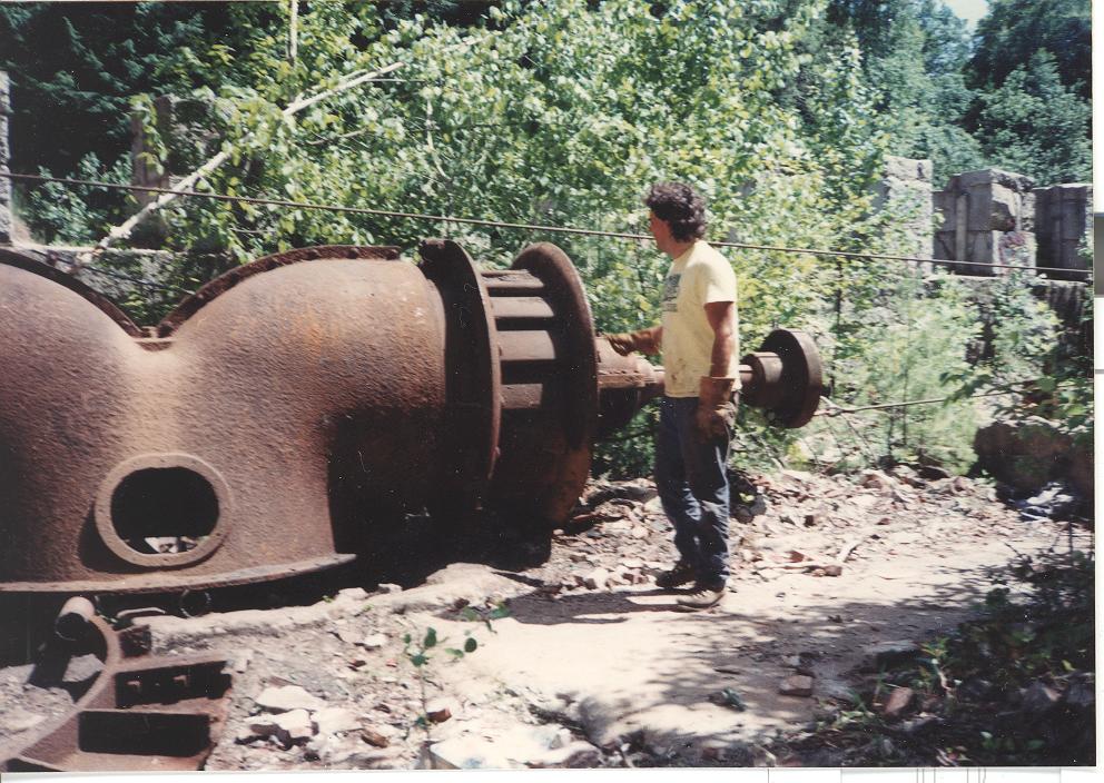
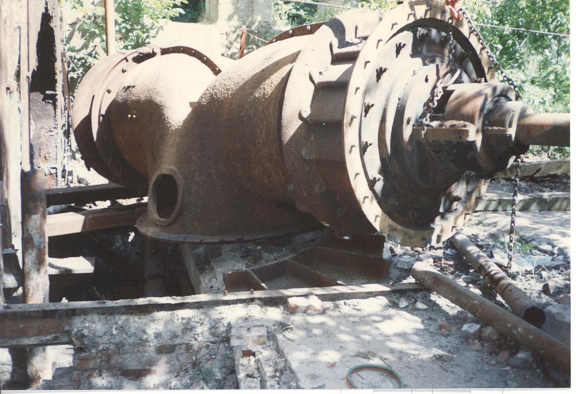
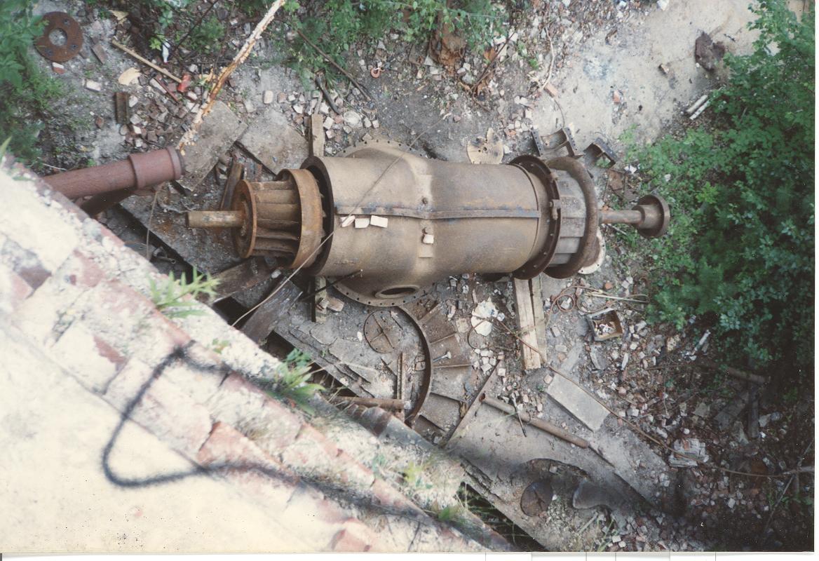
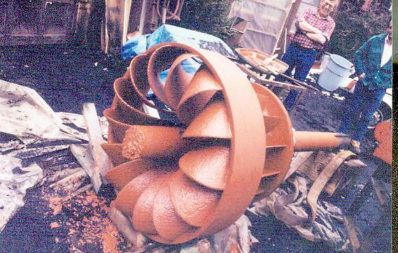
Water turbine- there were two Rodney Hunt Type 80, Francis turbines. Each turbine was in a camel back configuration with two runners on a common shaft. One runner was left hand and the other was right hand ie: mirror images so they would revolve in the same direction when placed back to back. The complete unit spun at 300 rpm and produced 1200 horsepower to run pulp beaters.
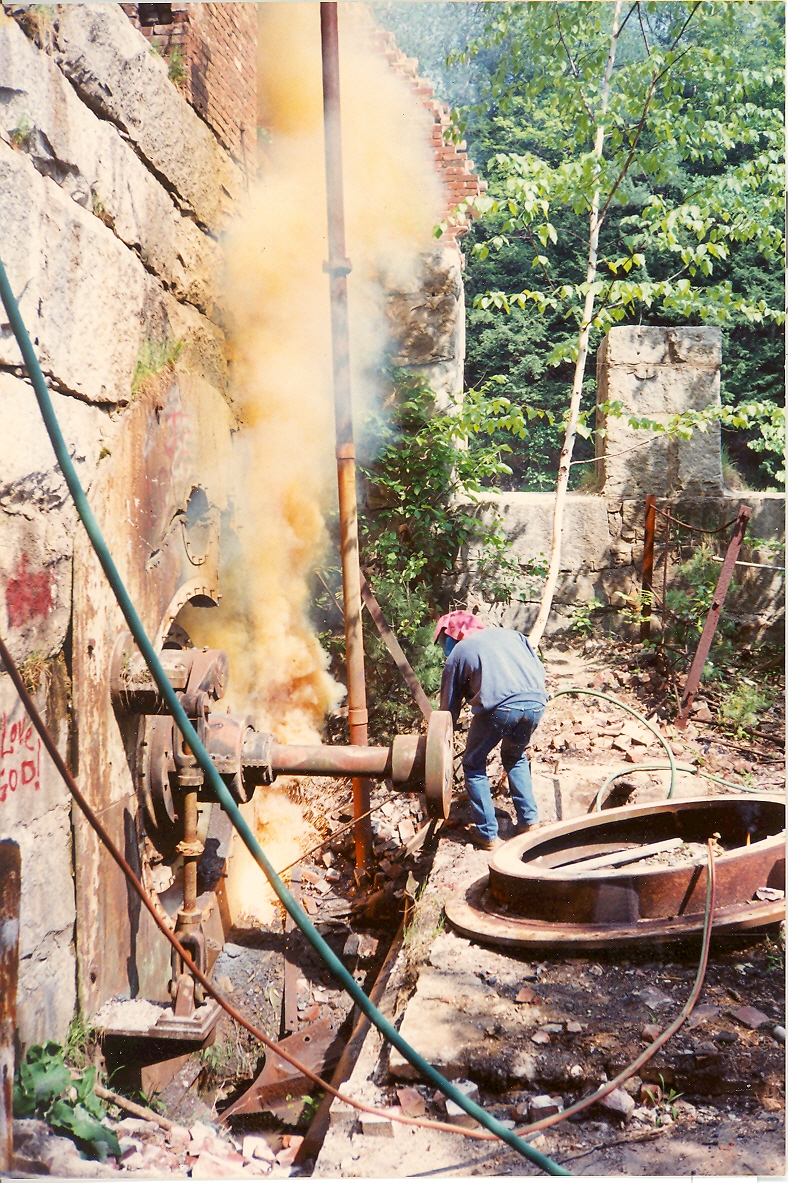
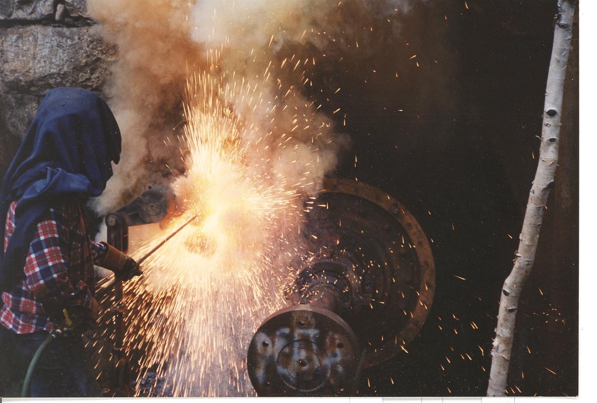
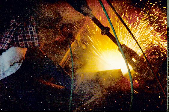
Molten cast iron being sprayed through the air. One ten foot bar will burn a slot through 3 inch thick cast iron 1/2 wide by 18 inches long.
Burning bars fed by liquid oxygen. Mr. Fay and Mr. Hobbs fed by gatorade!!!
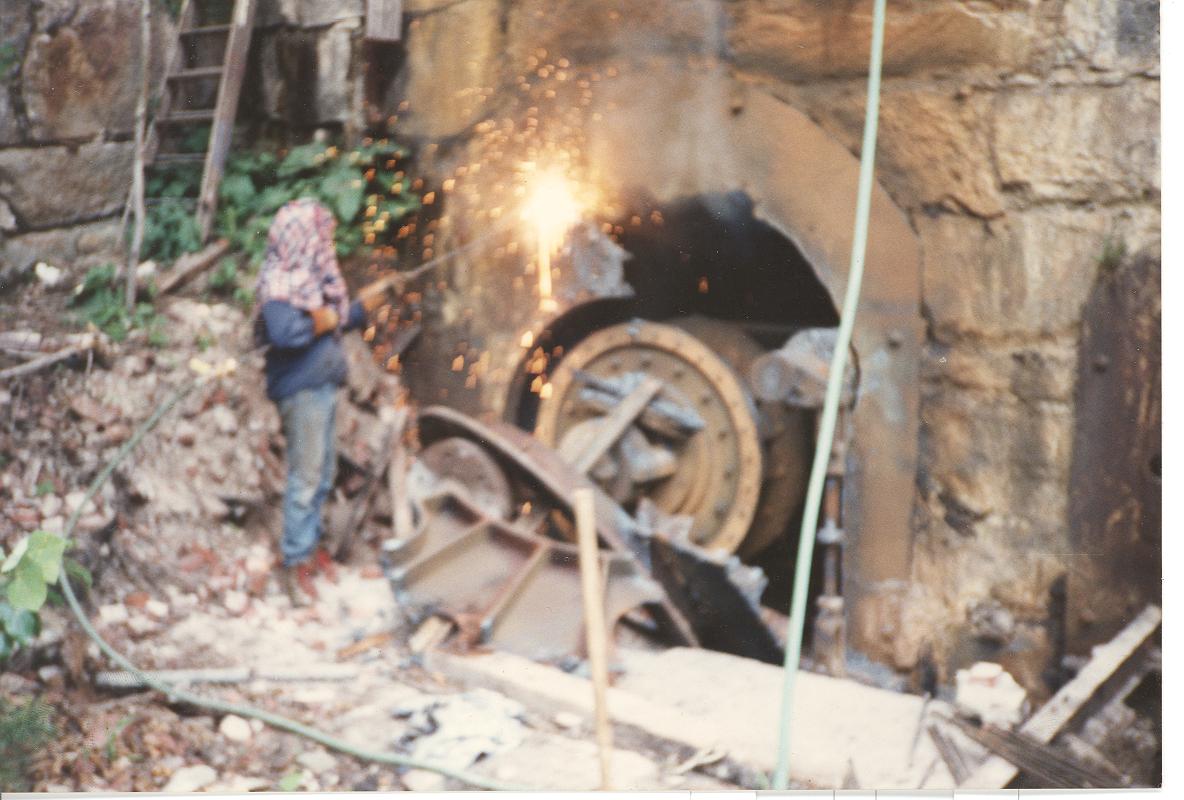
Almost done on the river side burning.
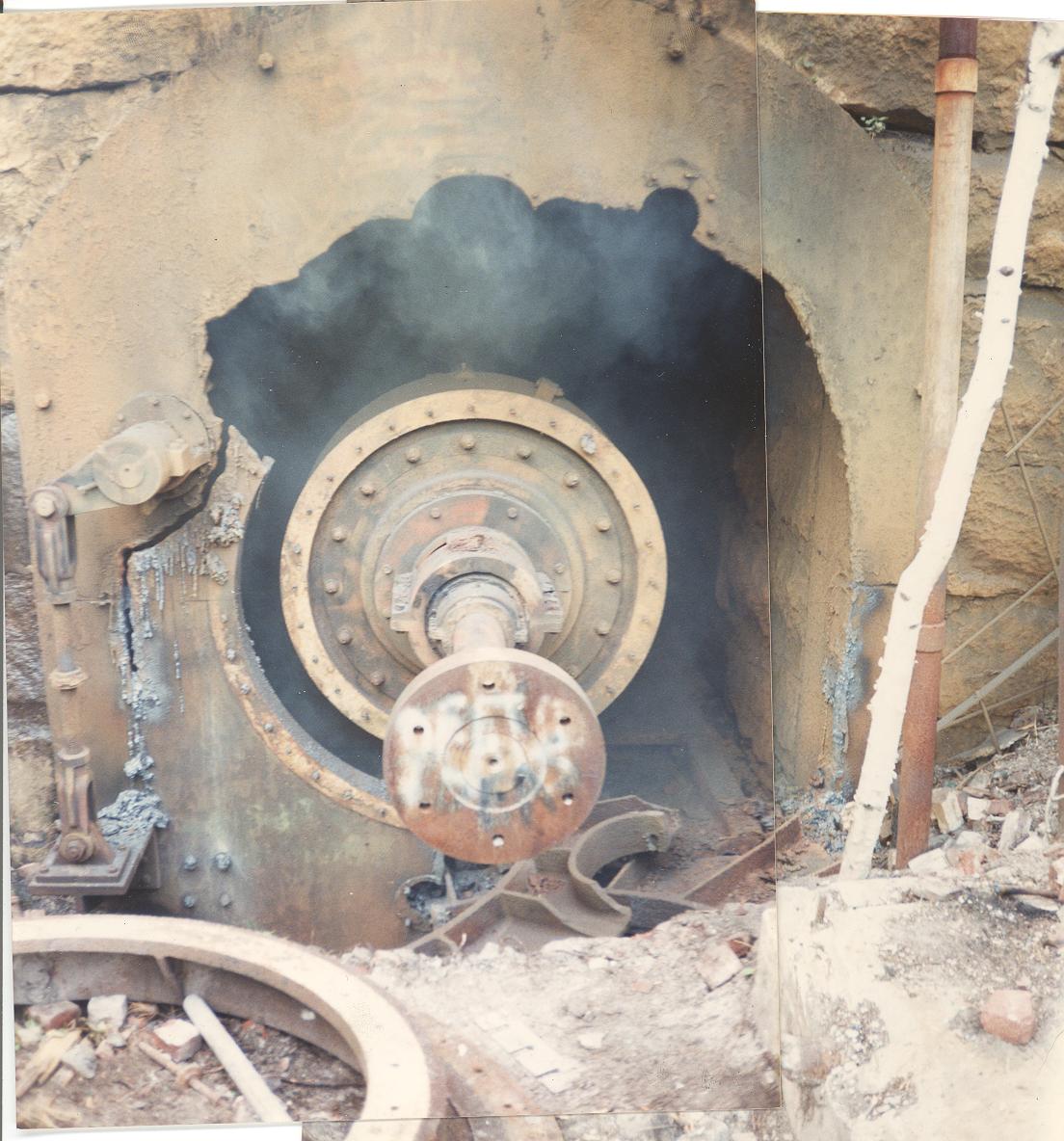
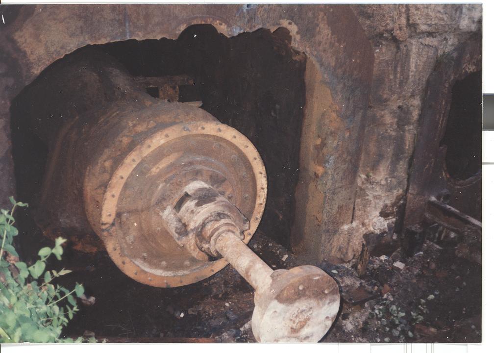
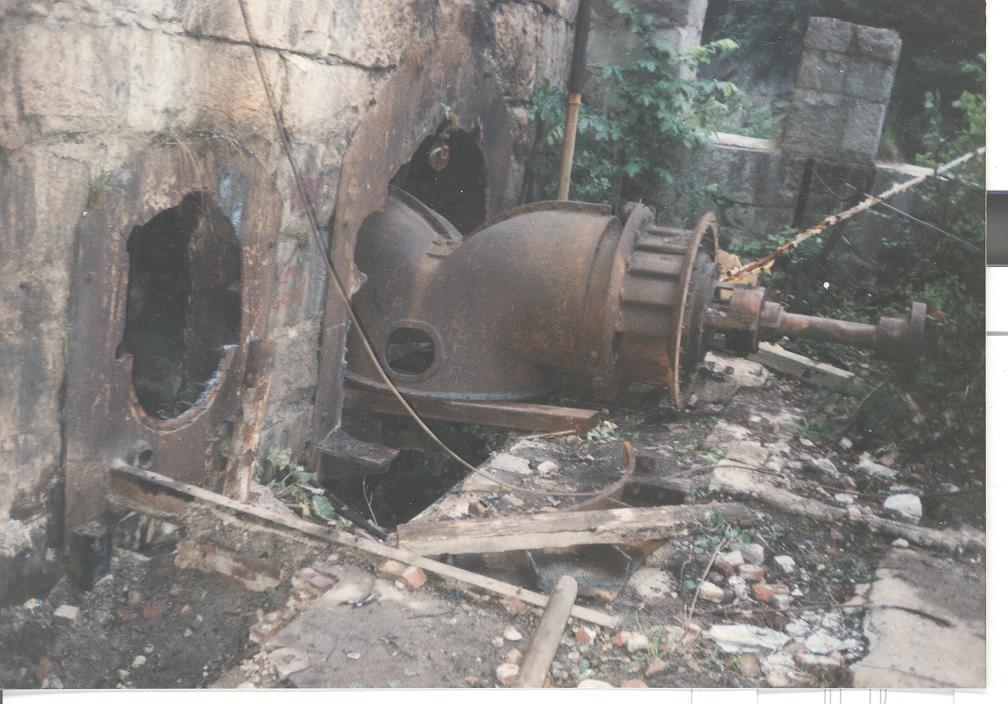
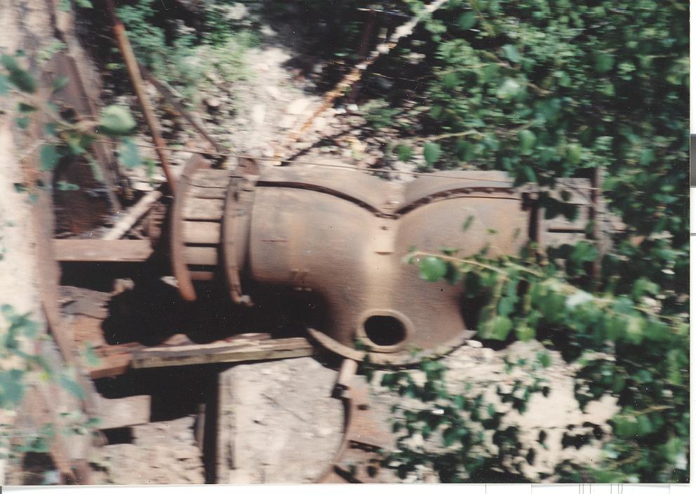
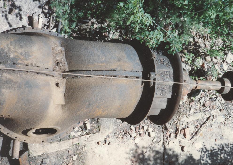
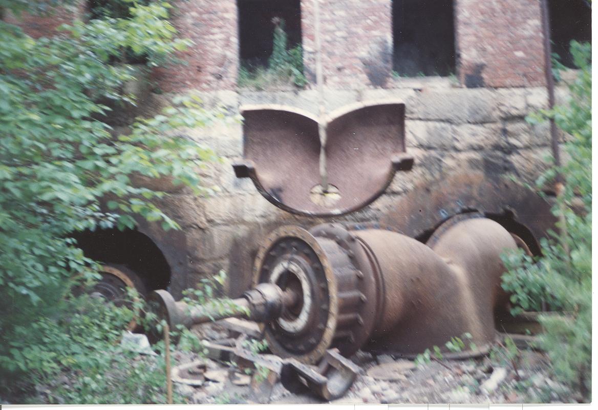
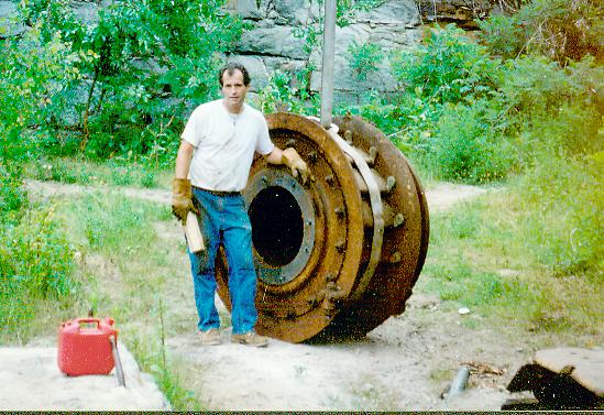
The beast exposed in its lair.
The Lima 34 Crane on top of the dam. On one side it drops 30 feet to the cellar floor. On the other side it drops 15 feet to the sand in the forebay. The top width is 15 feet.
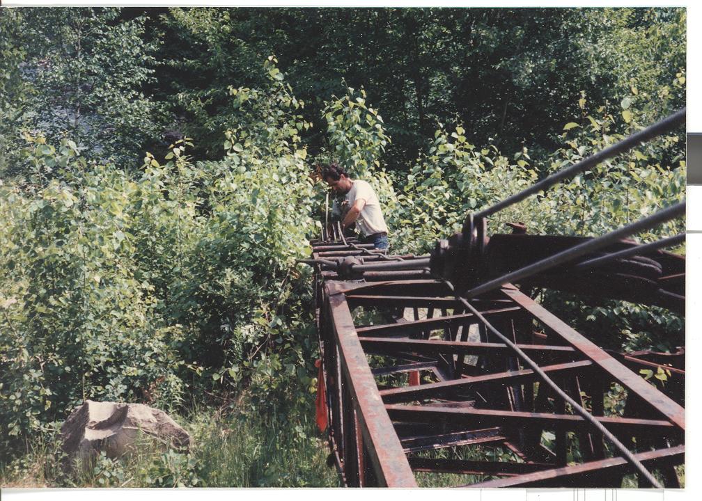
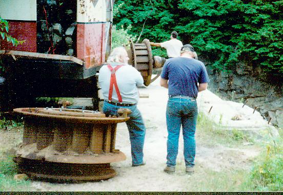
Mr. Hobbs tieing off the crane cable to some junk machinery. The LIMA is an old lady with a live stick. The cable lifts the boom up but the weight of the load and boom brings the boom back down by gravity. The load line drum was sticky so we had to tie the line off to something heavy each time and lift the boom back up in order to unreel the drum.
Mr. Hobbs directing the crew (me!!!).
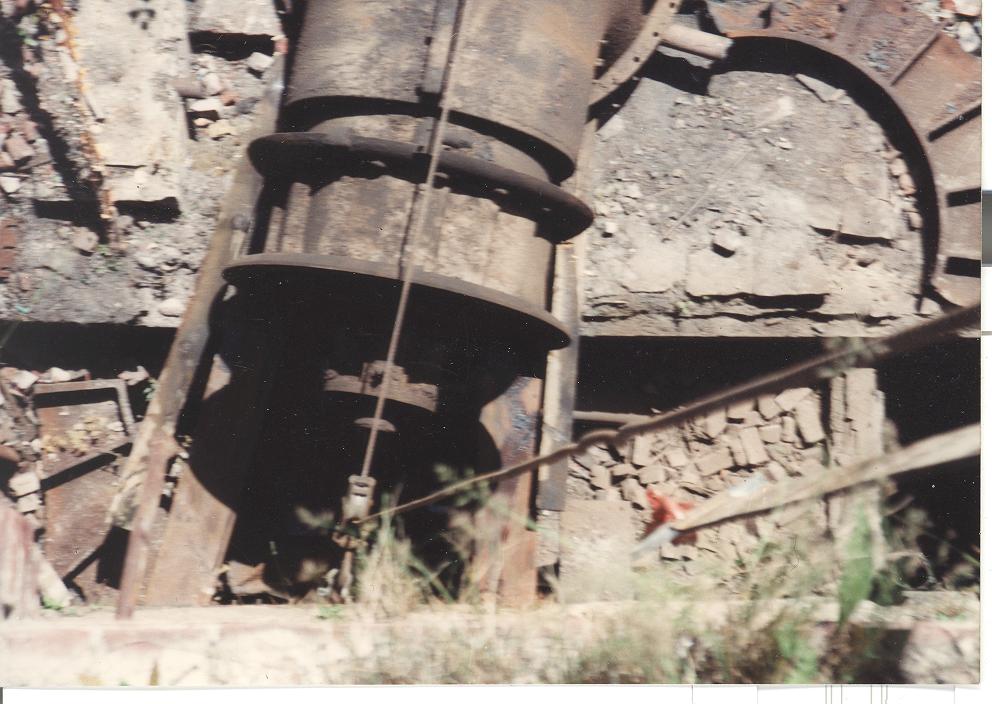
The beast reluctantly emerges from its lair! It had hibernated for 29 years. Here we had to stop because the pulley we were using to change the load direction extruded itself out of a piece of 8 inch pipe. The cable went crazy and tried to eat Mr. Hobbs. It is risky business doing jump rope with a 3/4 inch cable that has suddenly and explosively unloaded. (That is why we called him "Dangerous Dave!!!!). We re-rigged by putting a choker cable around one of the castellations and hooking the snatch block to the choker.
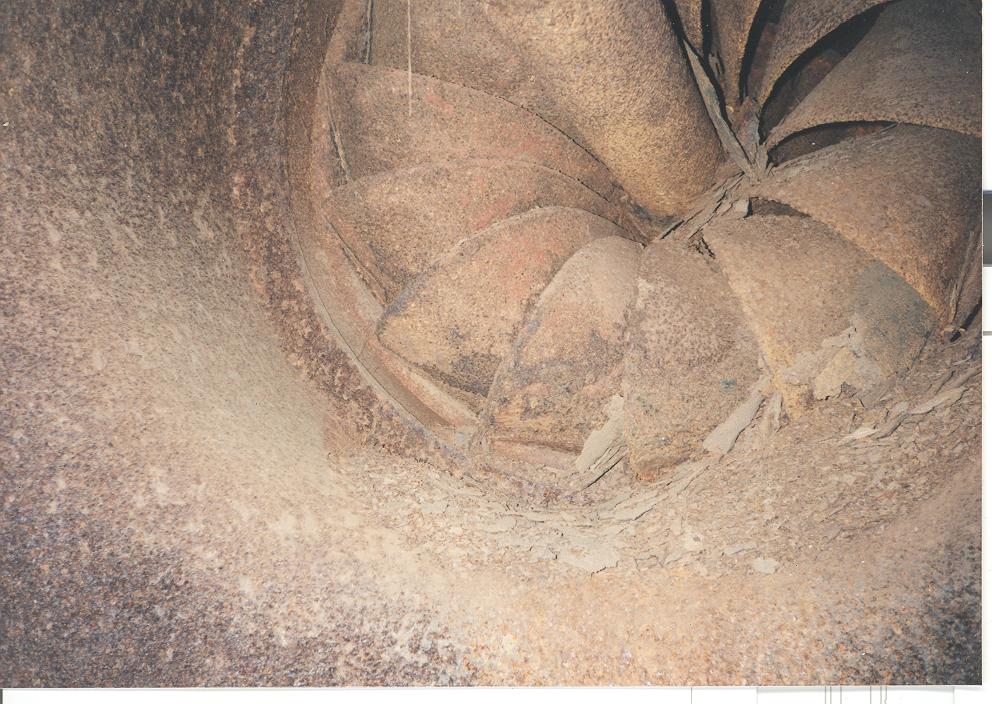
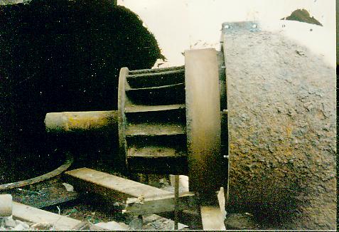
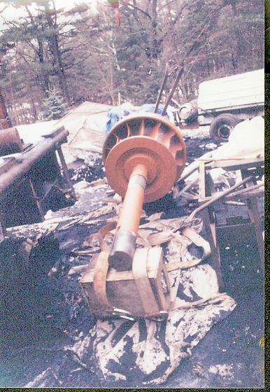
One of the runners. Note the heavy rust and scaling.
In order to remove the unit. We burned off the draft tube bed bolts. We used railroad jacks to lift the unit up. We slid these heavy box beams beneath it.
To transfer the load we burned a hole in this 8 inch pipe that was protruding from the floor. We inserted an eyebolt into the hole and reached down through the top of the pipe and screwed a nut on the back side. We hung the snatch block (a pulley that has a hook on one end with a side plate that can be removed to reeve a cable) on the eye bolt. As we pulled the cable with the crane the turbine started to slide up the box beams. It suddenly stuck. As I pulled harder, the nut on the eyebolt was pulled through the side of the pipe.
Another view of the impromptu extrusion process.
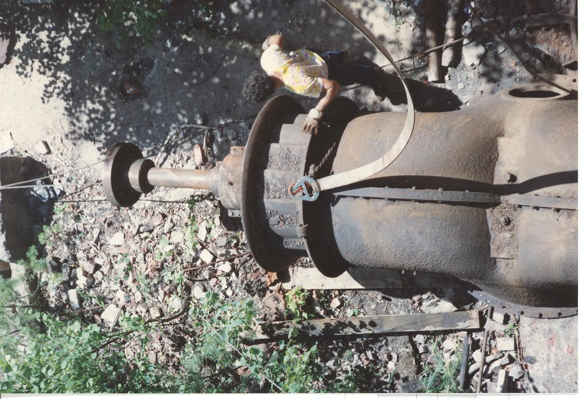
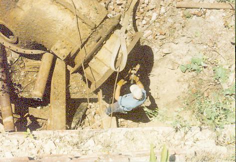
A bird's eye view of the cable. It is running down from the crane boom to a pulley mounted in the cast iron. The last thing I did when we finished burning off the cover was to burn a hole in the remaining cover large enough to insert a large eye bolt. We installed the eyebolt and hung a snatch block (pulley) to it. So the cable goes down vertically from the boom through the pulley. It then runs horizontally across the cellar floor to a second pulley mounted on a choker wrapped around the cellar wall on the far side of the cellar. It then runs back and is attached to another eye bolt on the turbine flange. As I pull up vertically with the crane, the force is transmitted horizontally to the front of the turbine and it is dragged sideways out of the hole. That's the theory anyways!!! Things get exciting when you are 30 feet in the air with a 30 ton crane sitting on a tiny footprint and you look over your shoulder to find the rear 1/2 of the tracks ate two feet off the ground because the turbine is not moving forward but the cable is pulling the boom over into the abyss!!!!!!
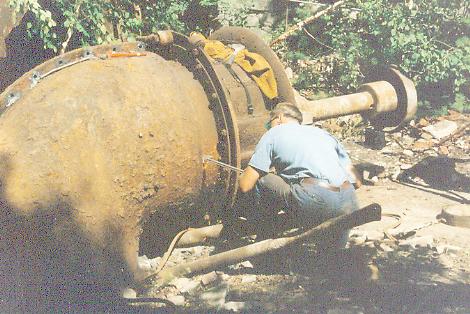
Mr. Hobbs with the beast. Note the pulley behind his head dangling from the eyebolt. Note the eyebolt on the far right screwed onto the end of the coupling. It has an orange shackle attached to it.
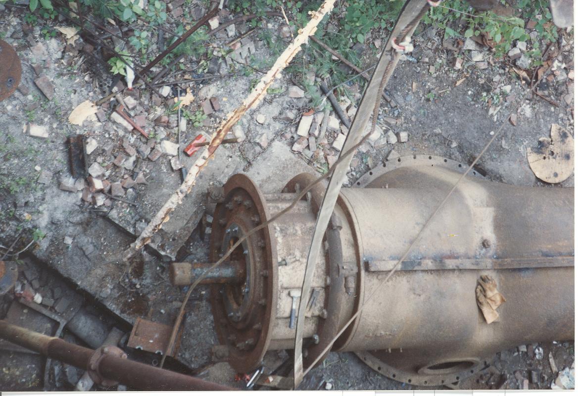
Here is a clear view of the cable systen running over to the snatch block at the far wall, turning 180 degrees and running back to the eyebolt on the turbine coupling. Note the giant pieces of pipe we are using as rollers to roll the turbine across the concrete cellar floor.
Another view of the cable system and large roller (see the circle beneath the oval manhole cover).
A bird's eye view of the removal. We had rollers, box beams and timbers all going at once.
Here is a great view of the choker wrapped around the castellation and the snatch block used to reverse the direction of force.
Here we tried to pick the complete unit out of the hole. It stayed put and the crane started to tip over. We decided to take the units out in pieces.
The unit is still complete.
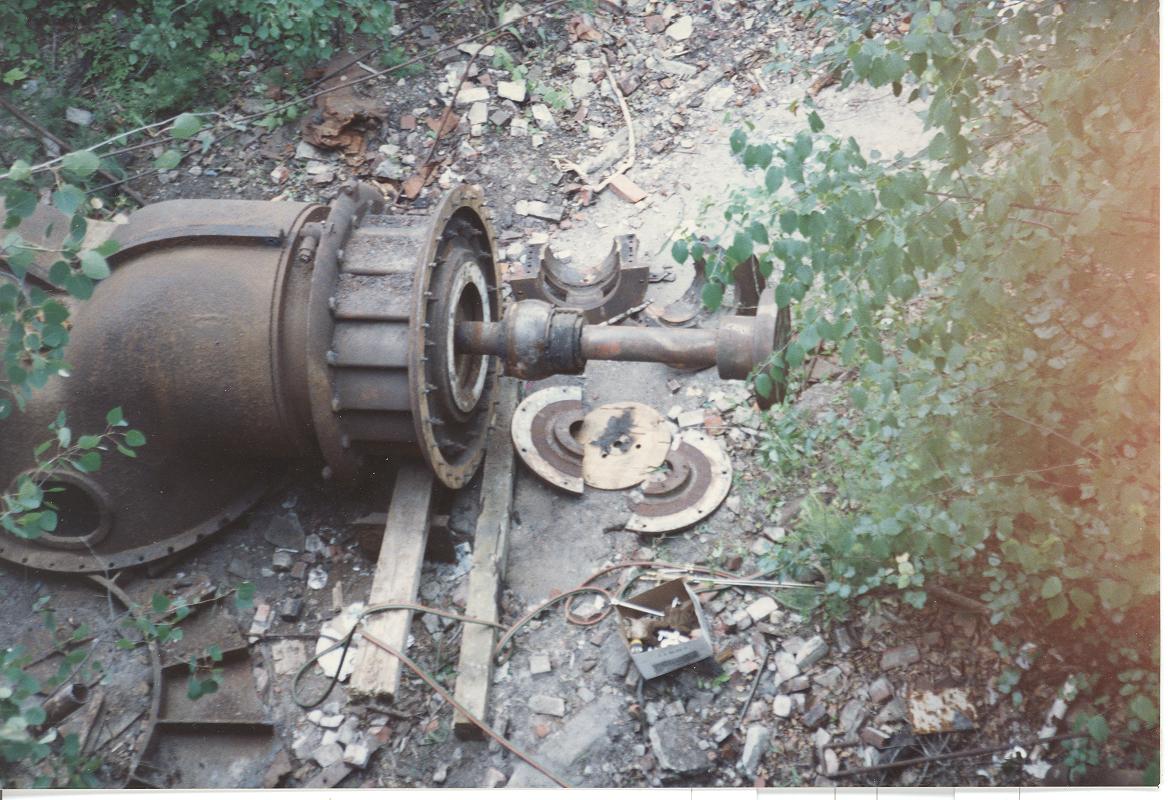
We have removed the wooden, lignum vitae, quarter block housing from the end of the gatecase.
We have removed the gatecase from one end and lifted it out of the pit.
We have dismantled the roller bearing and pulled the covers from the other end.
We have blocked up the mainshaft and removed one of the sides of camelback. By this time I was feeling like a bunch of ants that were devouring the carcass of the beast bit by bit!!!!
This was the heaviest and scariest pick. The two runners and one gatecase. The crane tilted up a bit on its treads, steadied out at a weird angle and the load came up out of the hole.
We start on the second lair. We had to hand shovel tons of brick and earth debris in order to expose the cast iron door. Note the white scum line on the face of the coupling from being buried. Note the manhole cover over the machine (I guess they were little people back than!!!). Also note the iron ring used to attach the turbine to the cover. We previously burned off all those bolt heads and pried the ring off.
Davis starts his surgical incision. Note the small pressure case to the right. The Clark's (of Clark's Trading Post Fame) 15 years previously removed a smaller turbine by drilling a two hundred holes in the little cover. They than smashed the cover with large sledge hammers. The result was the same but Davis and I preferred the thermite bars.
Somewhere at this time, I saw the shirt covering Davis' head on fire. I quickly took my quart of Gatorade and poured it on his head. He never even noticed!!!
The cover falls away in pieces.
Note the wooden step ladder propped up in the corner (OSHA approved!). We dropped the oxygen and acetylene bottles down from above. I was much stronger than and to remove the bottles we would sling them over our shoulders and carry them up the step ladder.
The shaft and linkage to the middle right control the turbine wicket gates. We had to carefully remove the shaft and bearings.
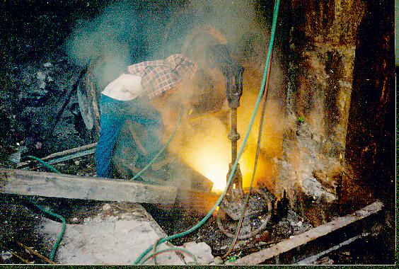
It looks like a scene from hell and maybe it was!!!
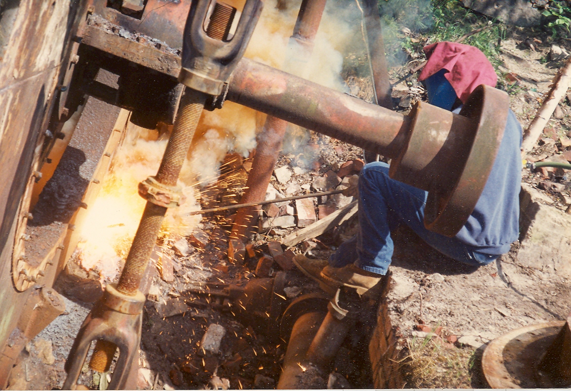
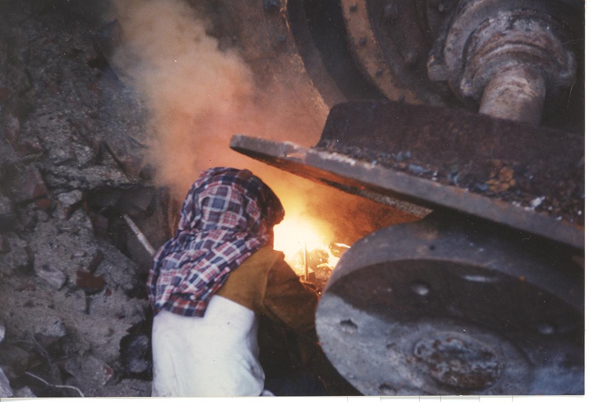
Close up and dirty thermite work.
Hell on earth!!!
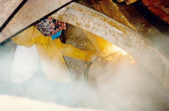
Mr. Hobbs flirting with the flames. Molten cast iron can be warm!!!
The burning bar is burning down to Davis' hand.
+ Davis dancing with the devil.
Things are warming up!
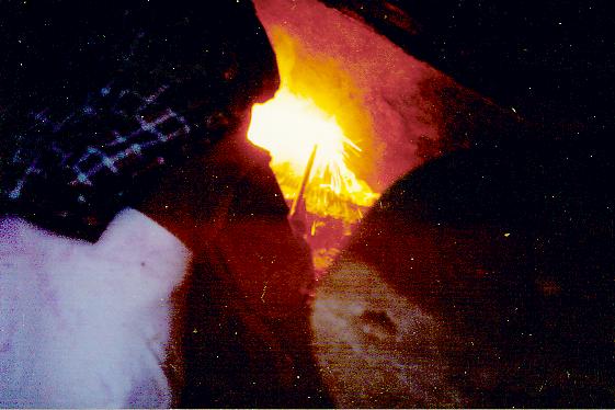
Look at the streams of molten cast iron. The camera caught the action. You could not look with your naked eyes. It was like looking at the sun. Also the streamers would have burned out your eyes.
It was tough getting to the burning area through the cast iron rubble.
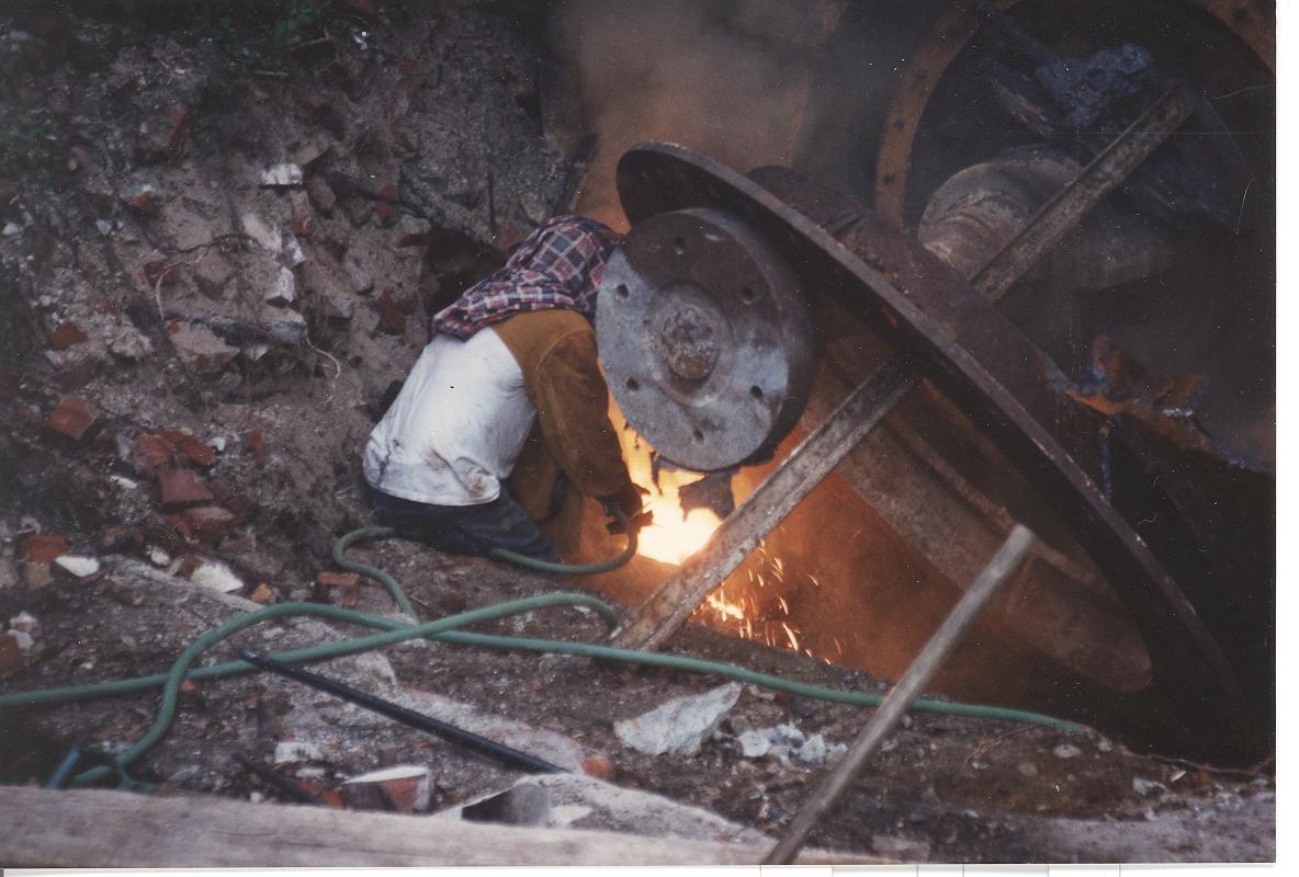
Here I have taken over from Davis and I am in the hot seat!!
Note the mass of molten cast iron on ground. Spare burning bars are stacked in the corner by the step ladder. The cutting torch is used to ignite the end of the burning bar.
I suppose we should have used face masks. We certainly did not need to take iron supplements for a while!!
Beast No. 2 exposed. Note the governor shaft control arm to the left. We have sliced off the shift ring arms. We now need to burn the bed flange bolts off. I think this is the day before Davis was burning in the back of the pit and we both simultaneously noted that the acetylene hose had burned through and there was a high pressure jet of flame burning one of Davis boots off his foot!! Between the eye bolt pulling out of the pipe that sent the 3/4 inch cable sawing across the basement floor and Davis being caught on the wrong side of the erupting acetylene hose I never understood why he did not enter the Olympics!!! Wow can Davis move really, really, fast!!!
Here we are receiving help from Johnnie Webster's brother, David of Southern New Hampshire Hydroelectric Development Company. Mr. Hobbs and Mr. Webster are dismantling the second unit.
Removing the cast iron quarter block assembly. David has burned the bolt heads off and is hammering steel wedges in the flange cracks.
David is using my 30 inch wrecking torch to burn off all the flange bolts in order to separate the camel back casing to reduce the weight that I need to pick with the crane.
Here Mr. Webster expertly wields the oxyacetylene torch and removes 40 year old bolts with a dexterity and ease which belies how difficult the process is! Mr. Webster and his brother John have developed many hydro electric sites through out New England and are skilled craftsmen and wiley business entrepreneurs!
Another exposed runner.
Mr. Fay has on the job training. He is learning the International Sign Language of cranes. A tight fist means "STOP". I usually only made that anal retentive sign when I looked behind me and noticed the crawlers tracks in back were three feet off the ground and the crane was ready to tip over into the abyss with me in it!!!!
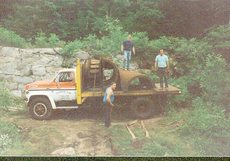
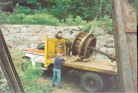
Here we are loading a unit onto Mr. Dean Yeaten's truck. Mr. Yeaten was wonderful and trucked both cranes and turbines for us. He jumped in and helped us rebuild the road and RR crossing into the gorge. His advice and encouragement were indispensable.
The end of a long day's work.
Extremely rare photo of Mr. Tom Clark of White Mountain Hydroelectric Company. He is directing one of the picks. Mr. Clark is the most experienced hydro owner/operator in New England. We were most fortunate to have him assist.
Here Mr. Clark, Mr. Hobbs and Mr. Dave Dearborn ruminate with the LIMA 34. Who says cranes can't talk?
Mr. Hobbs testing to see if the turbine will topple into the abyss. We are very safety conscience!!!
More rare views of the "un-photographable ones"!!!
Dave Dearborn and Tom Clark inspect the gatecase. David Dearborn helped us out more than anyone on this adventure. He was friend, advisor, mentor and more than anything, he steadfastly believed we could make it happen!!!!!!!!!!!!!!!!!!
Davis thought we could put one of these gatecases on either side of the crane and roll it back to Massachusetts.
Dean Yeaton's truck is in the background grinding up the old mill driveway with a serious load on the back of his truck. Davis is hooking the crane block to some junk in order to pull some slack back into the cables. Most cranes would have a sizable weight on the hook to provide this function. The little LIMA 34 had been a shovel. The previous owners had removed the shovel and installed a boom from a Linkbelt Speeder. As such the crane never had a crane weight on the back and never had a proper hook installed. Of course we were so ignorant about cranes that we did not know any better. It just goes to show, ignorance is bliss!!!"
Dean Yeaton, his son and Davis loading more parts.
And more parts. We had a constant source of tourists towards the end. It was like a weird NASCAR event, everyone kept wondering when we we would topple into the abyss, crash and burn!!
Mr. Hobbs is unhooking the giant 50 ton nylon strap from around a gatecase I had pulled from below.
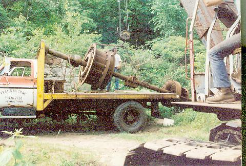
Mr. Fay sets the shaft assembly onto Mr. Yeaton's truck for transportation out of the gorge. It must have looked odd to the State Police going down the road with the runner assembly hanging off the back of his truck like that.
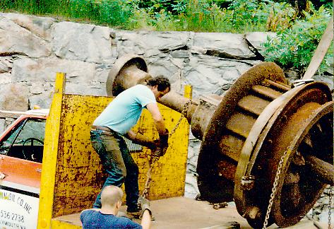
Young Mr. Yeaton and Davis securing a tricky load.
Taking the slack out of the chains.
Look out for the snap on that binder. It can take your teeth out.
Another load goes out.
A final view looking straight down the face of the forebay wall with the turbines removed. We left a lot of scrap metal on the ground.
We sold one of the turbines to Pioneer Hydroelectric Company in Ware, Massachusetts. We were than hired to refurbish the turbine and install it. The following are photos of the job.
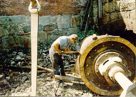
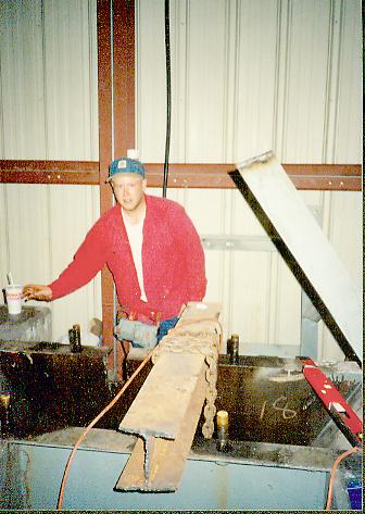
Here we have white blasted and primed one of the runners. We had to cut the shaft in order to part out one of the double runners. My friend, mentor and father-in-law, Nic Reitzel and Davis look over the work.
Another view from the other end. We had a horrible time getting the 36 inch diameter coupling off the shaft. We had two 100 ton bottle jacks between the runner and the bottom of the coupling. We had a 250 ton porta-power on top of the coupling. We heated the coupling up red hot. We jack that coupling up to 450 tons when suddenly there was an enormously load crack and the coupling split in half and fell off!!!!
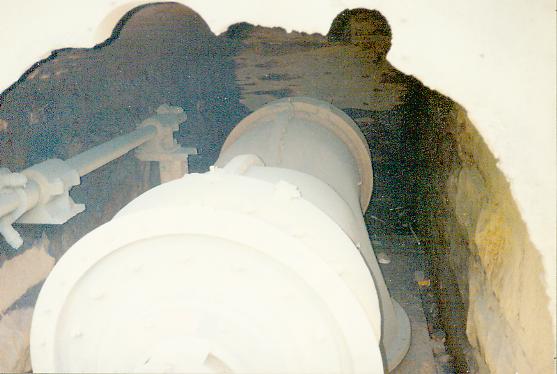
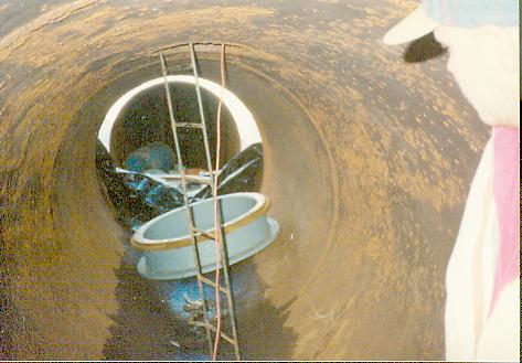
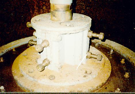
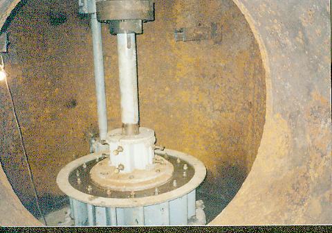
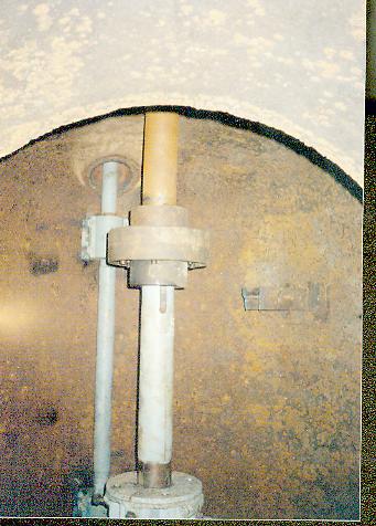
Various views of the rebuilt, 38 inch diameter, Rodney Hunt, Type 80 from Livermore Falls being installed at Pioneer Hydro in Ware, MA during March/April 1993. Here we are looking up the penstock, to the temporary roof hatch, we cut in the top of the penstock. This allowed us access to rig the old 30 inch Samson unit out and the new turbine parts in. The turbine throat ring is in the foreground.
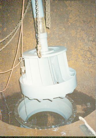
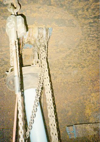
Here the reconditioned runner is being held up by a chainfall. We are getting ready to slide the throat ring onto the spool piece so that we can lower the runner into the throat.
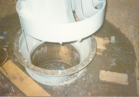
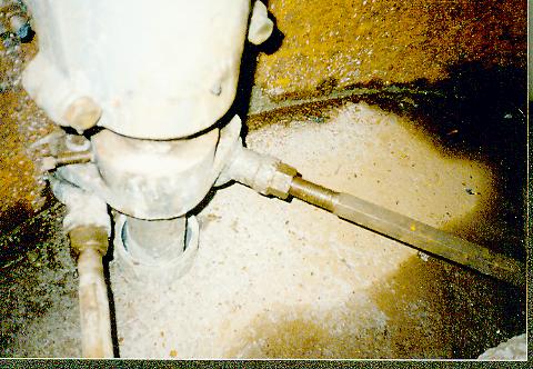
A close up of the spoolpiece. It was designed to convey the discharge water from the new turbine to the old Samson's draft tube. The Type 80 had a larger throat diameter than the 30" Samson wheel it was replacing. PHI did not want to replace the draft tube. We made a slight reducing section that speeded the water up before going into the old draft tube. The energy was than recovered in the old draft tube. This worked splendidly. We saw no reduction in power from that predicted by Rodney Hunt's power tables. Note the frozen tailwater in the bottom of the draft tube. The wooden blocks are frozen to the floor of the pressure case. Ambient outside temperature was -18 degrees F. Why do Davis and I always end up playing in river beds when it is below zero temperatures???
Here, young Mr. Hobbs is operating the big Hilti hammer drill. He is exposing the top of the pressure case so we can install the new gateshaft.
A picture of the rigging tackle we used to rig in the turbine runner(3800 pounds). The chainfall is actually in a hole burned in the top of the pressure casing. It is suspended by the I-beam in front of Jason Hobbs.
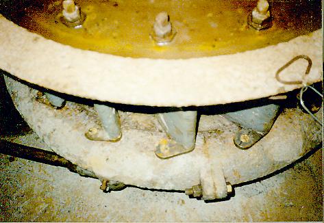
The rebuilt pressure case. We sandblasted all parts and primed and painted them with a two part epoxy paint. All pins and bushings were replaced. Mr. Hobbs made all the gate hinge pins and Mr. Fay made all the bronze eccentric pins.
A view of three gate links that are fabricated from steel that we replaced.
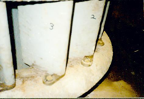
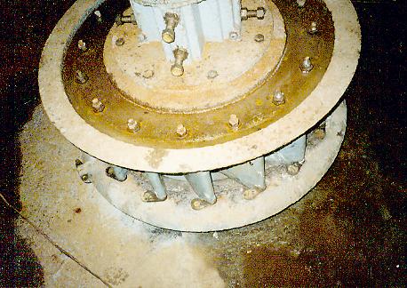
A view of the quarter block assembly. This contains blocks of lignum vitae wood from South America that serve as the shaft bearings under water.
A view of the rebuilt turbine. Note the gate shaft in the background. The coupling came from Appleton Mill in Lowell. It took me three hours to burn through the two 8 inch shafts with my wrecking torch. Retrieving the coupling halves from Appleton was an adventure in itself. Mr. David Wright of Ware River Power Company Inc. assisted us at Appleton and we were very grateful.
Note the new concrete floor surrounding the spool piece. We had 3 1/2 cubic yards of concrete poured down the penstock. Sometimes, Davis and my light bulbs, dim a little. It certainly happened that day. We ordered the concrete. We installed the concrete truck's chute into the access hole. Then Davis and I got our shovels and hoes and went down into the pressure case with no other way out. We told the driver to start pouring. 3 1/2 cubic yards is a lot of concrete!!! Especially in a tight place. As it was pouring down the penstock it started to bunch up. Then, to our horror it started to fill the penstock up instead of flowing towards us. It happened so quickly that the truck driver could not hear us. We jumped up into the penstock and literally hoed for our lives. We finally got it down into the pressure case and the flow from the truck stopped. I was a zombie going home that night!!!
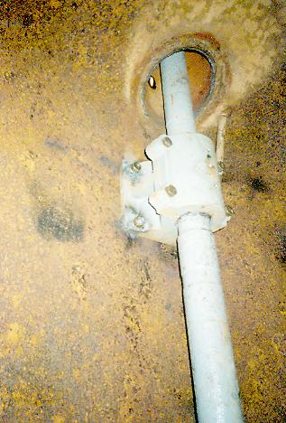
View of the base of the new gateshaft. The governor shaft was under hung and it would have been frozen into the new concrete. Davis installed a pipe chase for the shaft to sit in and to prevent the new concrete from touching the shaft. Note the new hexagonal gate operating arms. People are always making them out of round stock. You need to use a pipe wrench to adjust them and it always makes horrible marks on the steel. I decided to use hexagonal stock so you could use a big adjustable wrench on them.
The new coupling halves we retrieved from Appleton Mills. The governor shaft from Livermore Falls is seen in the background. We turned it on end, in a vertical configuration.
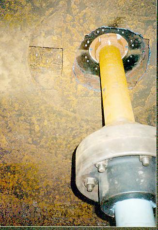
The new chase that we welded to the top of the pressure case in order to allow the governor shaft to penetrate the top of the pressure case.
We used a main stuffing box from Appleton Mills. We had to cut a large hole in the top of the pressure case in order to install the stuffing box.
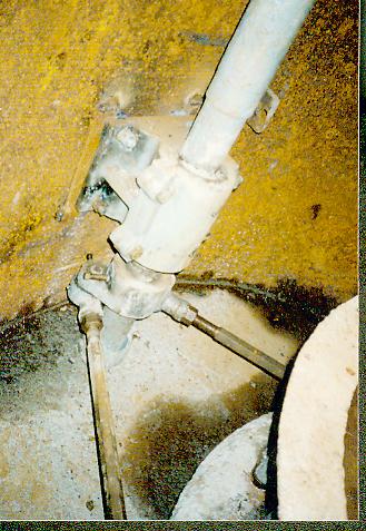
The double bell crank assembly. Note the ears face away from the pressure case. I am embarrassed to say that at Tannery Pond in Winchendon, MA. when we were installing a second Livermore Falls turbine, I installed the double bell crank with the ears facing the turbine. I could not figure out why the governor was jamming. Mr. Duncan Broatch of Summit Hydro Power and his friend Rick Mackowiack visited one day and were looking at the governor shaft. They pointed out that the double bell crank was installed backwards!!! It is good to have so many great friends in this business.
The Appleton Mills main stuffing box from the top side.
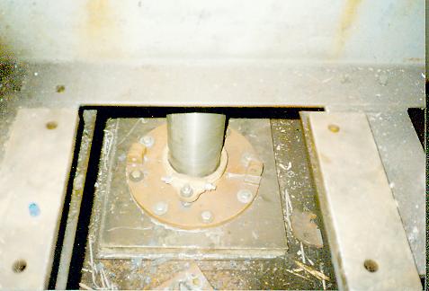
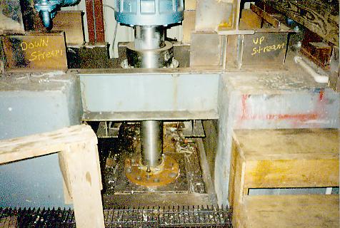
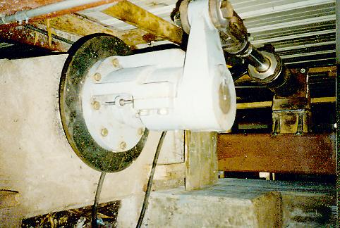
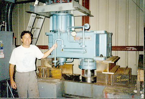
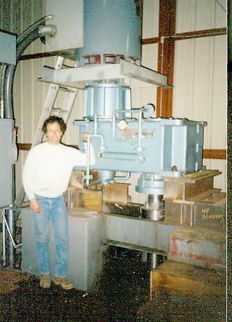
The new David Brown gearbox. This is used to increase the turbine speed to match the high speed Kato generator.
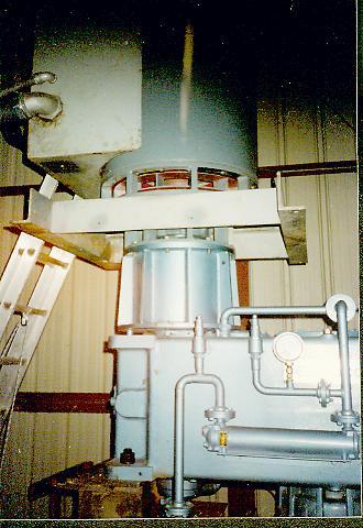
The Kato generator mounted on top of the David Brown speed increaser.
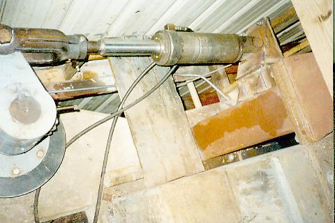
A view of the gearbox coupling on the end of the intermediate shaft.
Do you recognize this giant bell crank from the Livermore Falls pictures?
View of the new hydraulic actuator supplied and manufactured by Ware Machine Works. Thank you very much Mr. Pilch!!!
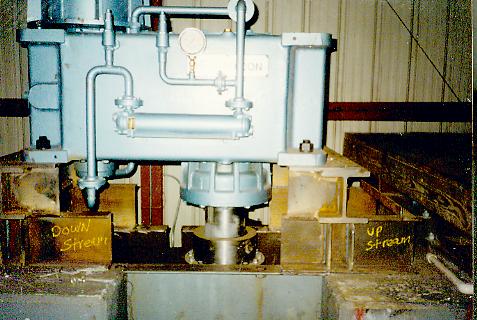
Mr. Fay and Mr. Hobbs in front of the new installation. We guaranteed 400 kilowatts and said it would generate closer to 500 kilowatts. It went on line and made 520 kilowatts!!! Good job Mr. Hobbs!!!!!!!!!!!!!!!!!!!!!!!!!!!!!!!! What a great business partner Davis has been!
The end
|
|
|